U-shaped aqueduct truss type all-steel formwork construction method

A construction method and steel formwork technology, applied in water conservancy projects, artificial waterways, infrastructure engineering, etc., can solve the problems of aqueduct wall structure damage, affecting the normal use of aqueducts, corrosion of steel bars, etc., to reduce installation and dismantling costs, Fast inspection and acceptance, and the effect of safe construction guarantee

Inactive Publication Date: 2021-12-03
广西建工集团海河水利建设有限责任公司
View PDF2 Cites 1 Cited by
  • Summary
  • Abstract
  • Description
  • Claims
  • Application Information

AI Technical Summary

Problems solved by technology

Secondly, in the traditional process, the inner and outer formworks are fixed by pulling bolts through the sides of the aqueduct. After the formwork is removed, there will be holes in the sides of the aqueduct, which will easily cause corrosion of steel bars and water leakage in the later stage. other security risks
When the corrosion of the steel bar reaches a certain level, the volume of the steel bar itself expands, and under the action of the expansion force, the concrete outside the tank wall cracks until it collapses, which destroys the structure of the aqueduct wall and affects the normal use of the aqueduct

Method used


Image

  • U-shaped aqueduct truss type all-steel formwork construction method
  • U-shaped aqueduct truss type all-steel formwork construction method
  • U-shaped aqueduct truss type all-steel formwork construction method

Examples


Embodiment 1

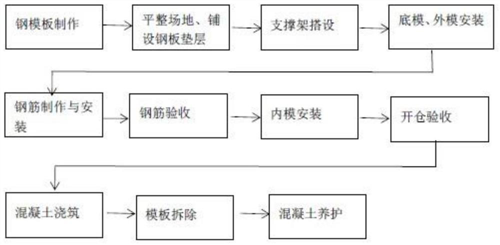
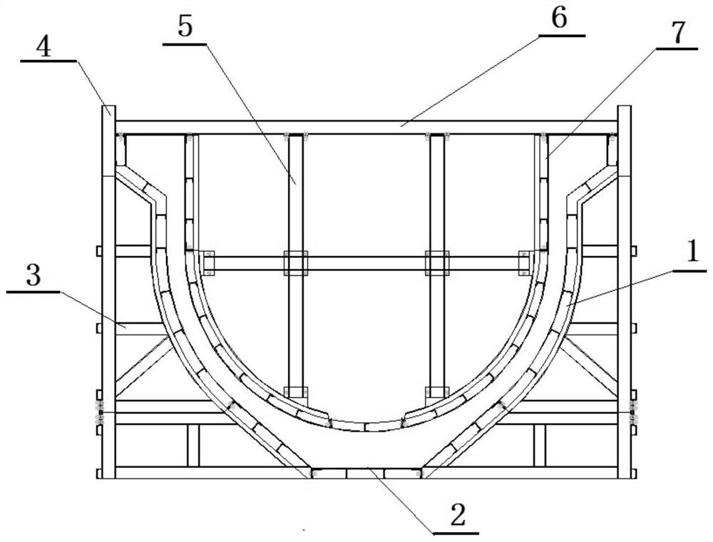
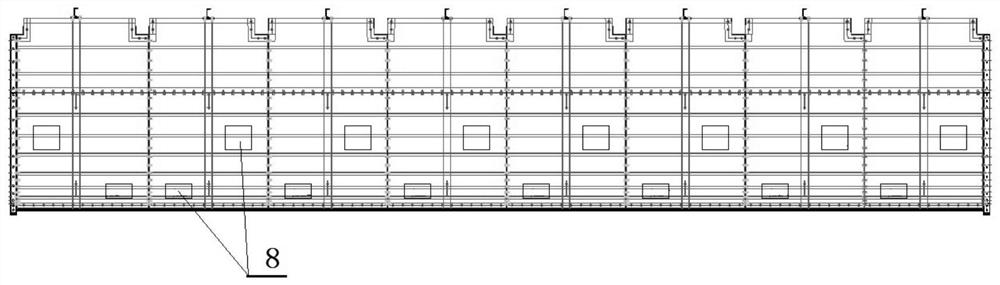
[0031] as attached figure 2 , attached image 3 As shown, the U-shaped aqueduct truss-type all-steel formwork construction method of the present invention is an example of a water conservancy project aqueduct project in Guangxi. The template used in the construction method includes a steel base plate, a support frame, an outer formwork 1, a base form 2 and an inner formwork 7; Mold 2, bottom mold 2 is located in the middle of the bottom of the entire aqueduct, and is used to connect the outer mold 1 that is arranged symmetrically on both sides. The inner surface of the outer mold 1 is arc-shaped to fit the U-shaped aqueduct, and the outer surface is vertical. Column, the support column is horizontally arranged to support the horizontal column B3 of the inner side of the outer mold, and the column B4 perpendicular to the horizontal column B is set; the inner mold 7 is located above the outer mold, and the inner mold 7 is a U-shaped structure. The bottom of the inner mold 7 i...


PUM


Abstract

The invention discloses a U-shaped aqueduct truss type all-steel formwork construction method. A formwork used in the method comprises a steel bottom plate, a supporting frame, outer side formworks, a bottom formwork and an inner formwork. The steel bottom plate is arranged at the bottom, the supporting frame is erected above the steel bottom plate, the bottom formwork is arranged above the supporting frame, the bottom formwork is located in the middle of the bottom of the whole aqueduct formwork and used for being connected with the outer side formworks symmetrically arranged on the two sides, the inner side faces of the outer side formworks are in an arc shape attached to a U-shaped aqueduct, and the outer side faces of the outer side formworks are vertically provided with supporting columns on the inner sides. The inner formwork is arranged above the outer formwork, a reinforcement cage is arranged between the inner formwork and the outer formwork, and a U-shaped aqueduct pouring cavity is formed between the inner formwork and the outer formwork; and the inner formwork is of a U-shaped structure, and a plurality of pouring holes are formed in the inner formwork. According to the U-shaped aqueduct truss type all-steel formwork construction method, one-time forming construction of aqueduct reinforced concrete is achieved through the formworks, the stable structure guarantees the forming section of the aqueduct, and the pouring holes are reasonably formed so that the flow passing face of the aqueduct can be smooth and flat; and the whole truss structure is not provided with concrete-penetrating opposite-pulling steel bars, so that the hidden danger of overflowing leakage corrosion of the aqueduct caused by the concrete-penetrating opposite-pulling steel bars is solved.

Description

technical field [0001] The invention relates to the technical field of building construction, in particular to a U-shaped aqueduct truss-type all-steel formwork construction method. Background technique [0002] An aqueduct is an overhead water delivery structure that conveys water across rivers, roads, and mountains. It is one of the most widely used crossing structures among hydraulic structures in irrigation areas. In the traditional construction process of the aqueduct, while requiring a lot of manpower, material resources and funds, the construction progress is also extremely slow. The profile of U-shaped aqueducts is composed of circular arcs and straight lines, with complex structural lines, large spans, and relatively thin walls. [0003] The current construction method is to use wooden formwork and pour the entire aqueduct in stages. The general process is: firstly formwork the structure of the bottom 1 / 3 section, then formwork the middle 1 / 3 section, and finally ...

Claims


Application Information

Patent Timeline
Patent Type & Authority Applications(China)
IPC IPC(8): E02B5/02E02D15/02
CPCE02B5/02E02D15/02
Inventor 闫志勇袁小军刘祥喜莫开生钟爱华马轲莫大源覃宏春旷星星黄文基雷贵健彭桂军
Owner 广西建工集团海河水利建设有限责任公司
Why Eureka
Try Eureka