
Preparation method of wind power blade

A wind power blade and root method technology, applied in wind power generation, final product manufacturing, sustainable manufacturing/processing, etc., can solve problems such as installation interference, large deformation, misalignment of screw sleeve holes and main engine bearing connection holes, etc., to achieve blade The effect of reduced root deformation and high counterboring precision

Active Publication Date: 2021-12-03
JILIN CHONGTONG CHENGFEI NEW MATERIAL
View PDF8 Cites 5 Cited by
  • Summary
  • Abstract
  • Description
  • Claims
  • Application Information

AI Technical Summary

Problems solved by technology

[0004] The purpose of the present invention is to provide a method for preparing wind power blades to solve the problems of large deformation caused by the existing pre-embedded blade root technology, and installation interference caused by misalignment of the screw sleeve hole and the connection hole of the main engine bearing

Method used


Image

  • Preparation method of wind power blade
  • Preparation method of wind power blade
  • Preparation method of wind power blade

Examples


Embodiment Construction

[0049] The following is further described in detail through specific implementation methods:

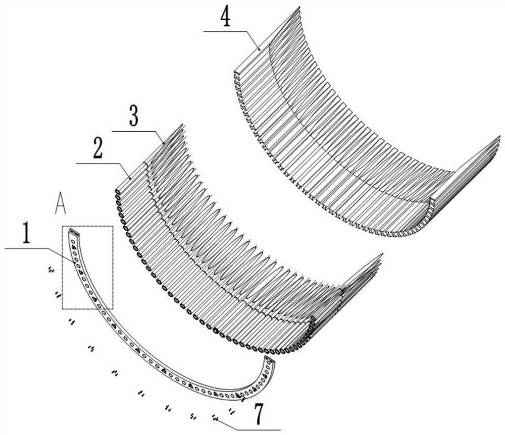
[0050] The reference signs in the drawings of the specification include: connecting flange 1, screw sleeve 2, wedge block 3, UD block 4, L-shaped groove 5, connecting hole 6, countersunk bolt 7, second counterbore 8, connecting flange Mounting hole 9, sealing ring 10, SS embedded parts 11, SS surface embedded blade root mold 12, embedded blade root flange 13, lock buckle 14, embedded blade root bolts 15, PS surface embedded blade root mold 16. Press block 17, first positioning block 18, first positioning groove 19, lock groove 20, first threaded hole 21, second positioning groove 22, second positioning block 23, SS shell mold 24, SS embedded leaf Root 25, blade upper mold 26, blade lower mold 27, upper steel frame 28, lower steel frame 29, first positioning component 30, support component 31, grasping component 32, first axial positioning block 33, second axial positioning Block 34,...


PUM

PropertyMeasurementUnit
thicknessaaaaaaaaaa

Abstract

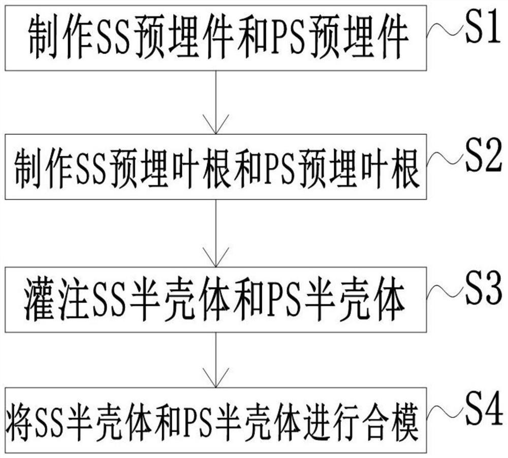
The invention belongs to the technical field of wind power blades, and particularly discloses a preparation method of a wind power blade. The preparation method comprises the following steps that at S1, an SS embedded part and a PS embedded part are manufactured, specifically, the SS embedded part and the PS embedded part each comprise a connecting flange, a plurality of sets of thread inserts, a UD block, a wedge-shaped block and a sealing ring; at S2, an SS embedded blade root and a PS embedded blade root are manufactured; at S3, an SS half shell and a PS half shell are poured; and at S4, the SS half shell and the PS half shell are subjected to mold closing, specifically, the position of an embedded blade root flange is adjusted on a blade mold, and then the SS half shell and the PS half shell are bonded, and after bonding and curing, the embedded blade root flange is removed, demolding is performed, and finally the blade is manufactured. A positioning tool is arranged on the blade mold, and the positioning tool can position and adjust the position of the embedded blade root flange. According to the method, the problems that the deformation amount is large, and installation interference is caused by dislocation of thread insert holes and a connecting hole of a main engine bearing due to the adoption of an existing blade root embedding technology can be solved.

Description

technical field [0001] The invention belongs to the technical field of wind power blades, in particular to a preparation method of wind power blades. Background technique [0002] There are two types of blade root structures for wind power blades: perforated and pre-embedded. The demand for high power generation has made the development of large megawatt blades a trend. Large megawatt blades mean larger rotor diameters and larger blade root interfaces. Considering the strength of the blade root, the blade root of the perforated method is not enough to ensure the integrity of the blade. Safety. The pre-embedded blade root technology gradually replaces the blade root drilling method; the existing pre-embedded blade root structure is a screw sleeve, UD block and wedge block installed in the middle of the layup, poured together with the layup, and the end surface of the blade root screw sleeve after demoulding Carry out flatness grinding, then install flanges and bolts, and fi...

Claims


Application Information

Patent Timeline
Patent Type & Authority Applications(China)
IPC IPC(8): B29C70/68B29C70/48B29L31/08
CPCB29C70/683B29C70/48B29L2031/085Y02P70/50
Inventor 谢磊秦梓程聂义张石强罗莎莎王建东王安鹏唐臣刘谷雨
Owner JILIN CHONGTONG CHENGFEI NEW MATERIAL
Learn More