
A polishing temperature control device, chemical mechanical polishing system and method

A technology of temperature control device and chemical machinery, which is applied in the direction of grinding device, grinding machine tool, manufacturing tool, etc., can solve the problems of heat loss of polishing liquid, excessive chemical action, and influence on wafer polishing effect, so as to improve uniformity and prolong The effect of service life

Active Publication Date: 2022-07-15
TSINGHUA UNIV +1
View PDF20 Cites 0 Cited by
  • Summary
  • Abstract
  • Description
  • Claims
  • Application Information

AI Technical Summary

Problems solved by technology

However, for chemical mechanical polishing, the chemical action between the chemical composition in the polishing liquid and the wafer surface needs to be carried out at a certain temperature. If the temperature is too high, the chemical action is too fast, and the chemical action and mechanical removal are out of balance, which will make the wafer Processing quality is greatly affected
[0005] In addition, during the process of moving the wafer from the loading cup to the polishing pad, there may be a temperature difference between the surface of the wafer and the surface of the polishing pad, which will cause heat loss from the polishing pad and the polishing liquid on it, and make the contact area of ​​the wafer The temperature of the polishing liquid is different from the temperature in other areas, which will also affect the polishing effect of the wafer to a certain extent

Method used


Image

  • A polishing temperature control device, chemical mechanical polishing system and method
  • A polishing temperature control device, chemical mechanical polishing system and method
  • A polishing temperature control device, chemical mechanical polishing system and method

Examples


Embodiment Construction

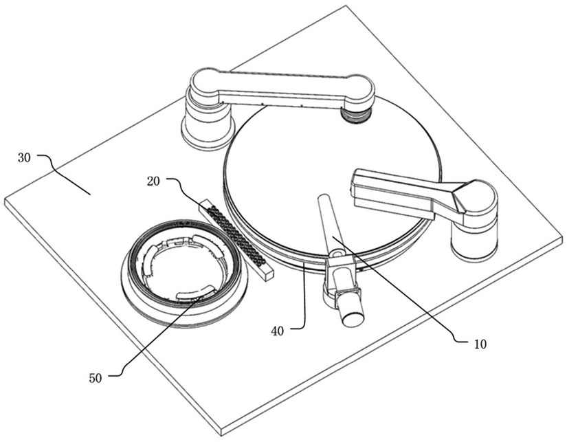
[0033] The technical solutions of the present invention will be described in detail below with reference to specific embodiments and accompanying drawings. The embodiments described herein are specific embodiments of the present invention, used to illustrate the concept of the present invention; these descriptions are all explanatory and exemplary, and should not be construed as limiting the embodiments of the present invention and the protection scope of the present invention . In addition to the embodiments described herein, those skilled in the art can also adopt other obvious technical solutions based on the contents disclosed in the claims of the present application and the description thereof, and these technical solutions include adopting any modifications made to the embodiments described herein. Obvious alternative and modified technical solutions.

[0034] The accompanying drawings in this specification are schematic diagrams to help explain the concept of the prese...


PUM

PropertyMeasurementUnit
thicknessaaaaaaaaaa

Abstract

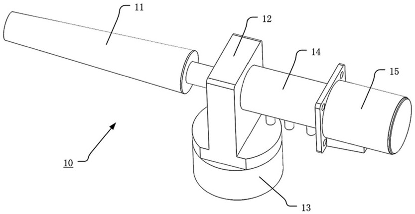
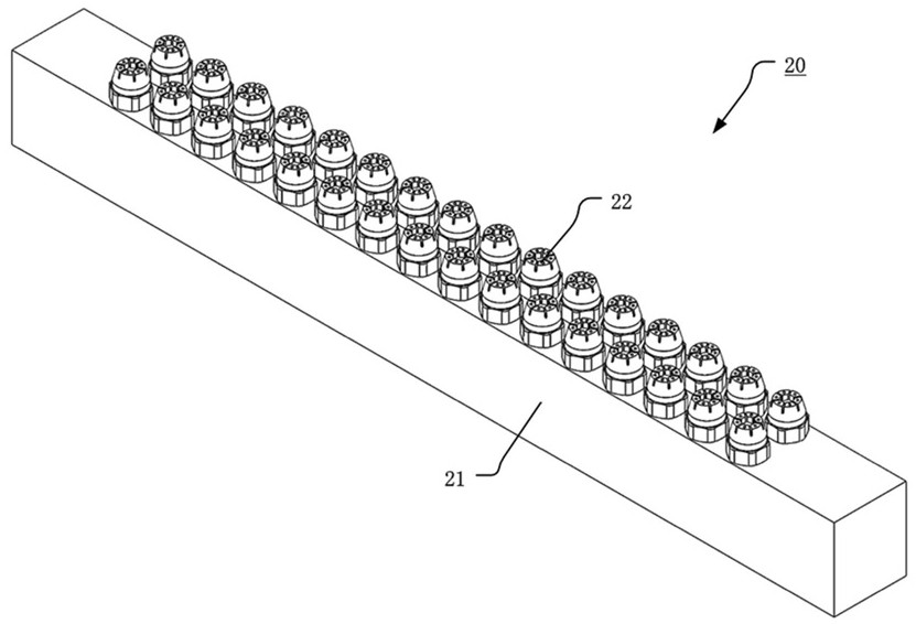
The invention discloses a polishing temperature control device, a chemical mechanical polishing system and a method. The polishing temperature control device includes a first temperature adjustment mechanism, which includes a heat transfer roller, a mounting seat and a driving seat, and the driving seat is arranged on the polishing The machine platen of the equipment, the mounting seat is arranged on the driving seat, the heat transfer roller is cantilevered on one side of the driving seat, the outer peripheral side of the heat transfer roller is in contact with the upper side of the polishing pad, and the rotating polishing The pad drives the heat transfer roller to rotate around its axis to control the temperature of the polishing pad and the polishing liquid; the second temperature regulating mechanism is arranged in the wafer transport path to spray fluid on the passing wafer to control the temperature of the bottom surface of the wafer.

Description

technical field [0001] The invention belongs to the technical field of chemical mechanical polishing, and in particular, relates to a polishing temperature control device, a chemical mechanical polishing system and a method. Background technique [0002] The integrated circuit industry is the core of the information technology industry and plays a key role in the process of boosting the transformation and upgrading of the manufacturing industry to digitalization and intelligence. A chip is the carrier of an integrated circuit, and chip manufacturing involves process processes such as chip design, wafer manufacturing, wafer processing, electrical measurement, cutting, packaging, and testing. Among them, chemical mechanical polishing belongs to the wafer manufacturing process. [0003] Chemical mechanical polishing (Chemical Mechanical Planarization, CMP) is a global planarization of ultra-precision surface processing technology. In chemical mechanical polishing, the wafer i...

Claims


Application Information

Patent Timeline
Patent Type & Authority Patents(China)
IPC IPC(8): B24B37/015B24B37/10B24B37/30B24B37/20
CPCB24B37/015B24B37/10B24B37/30B24B37/20
Inventor 路新春郑鹏杰赵德文
Owner TSINGHUA UNIV
Learn More