Adjustable cutting and weeding device for landscaping
An adjustable technology for landscaping, which is applied in the field of adjustable cutting and weeding devices for landscaping, can solve the problems of unsatisfactory lawn mowing efficiency and effect, and the inability to realize automatic walking lawn pruning and cutting, so as to facilitate lawn pruning operations and improve pruning Range, flexible adjustment effect
- Summary
- Abstract
- Description
- Claims
- Application Information
AI Technical Summary
Problems solved by technology
Method used
Image
Examples
Embodiment 1
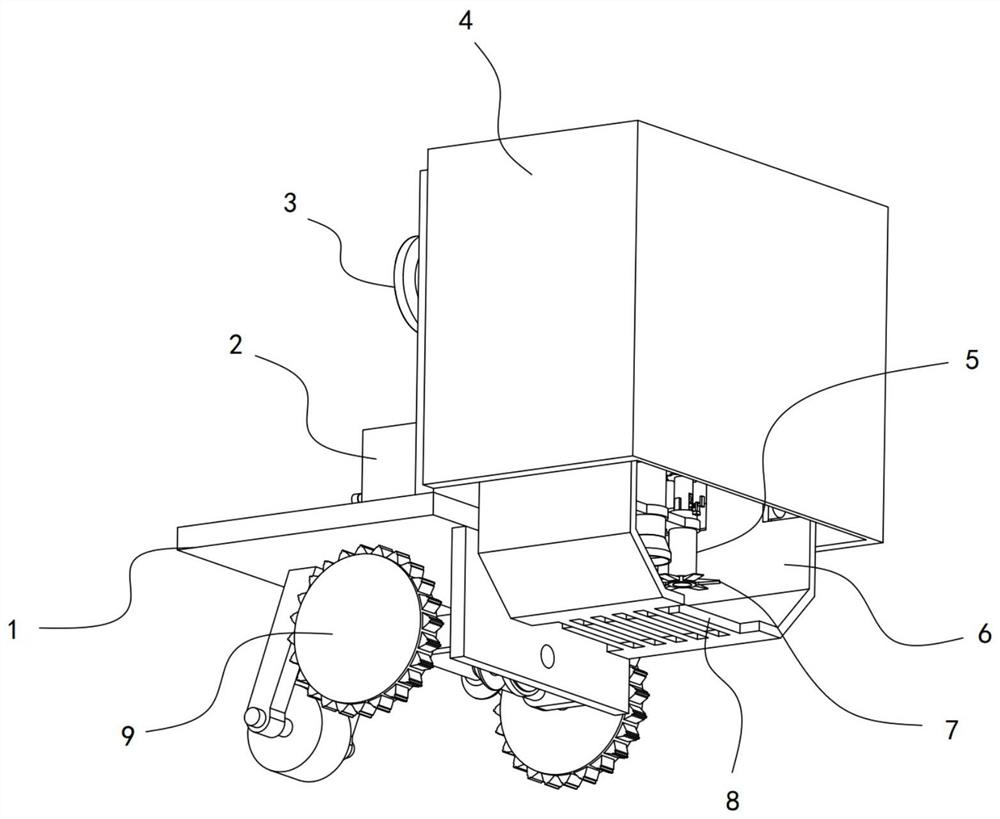
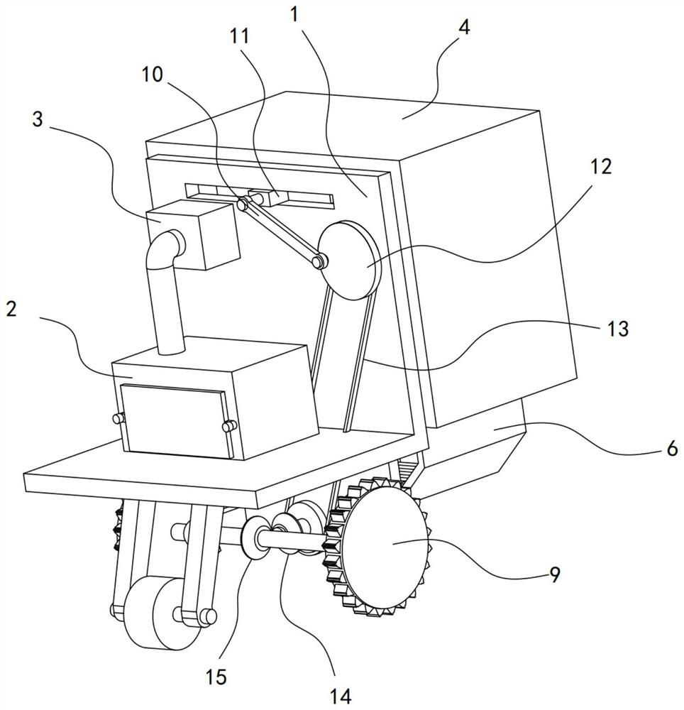
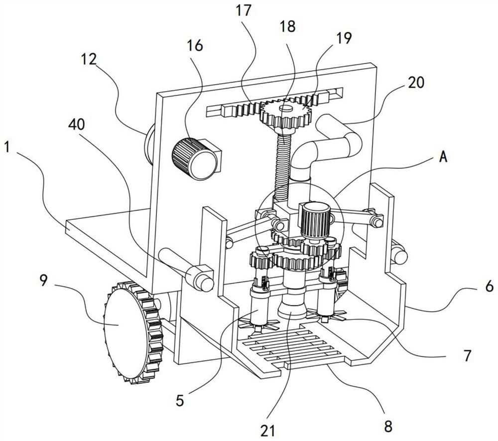
[0030] see Figure 1-8 , an adjustable cutting and weeding device for landscaping, including a carrier frame 1, a protective shell 4 is installed on one side of the carrier frame 1, and a walking wheel 9 is installed on the bottom of the carrier frame 1. It also includes a pair of hinged seats 40. On the turret 6 in the protective case 4, toothed plates 8 are fixed on the two turrets 6, and the two toothed plates 8 are interlaced. On the bearing frame 1, a lifting block 23 is vertically slid and installed, and the lifting block 23 is connected to the turret. 6 is hinged with transmission rod 24, and the bottom of lifting block 23 is provided with a rotating mechanism, and a pair of rotating shafts 30 vertically arranged are installed on the rotating mechanism, and the adjusting sleeve 5 is connected with the adjusting sleeve on the rotating shaft 30 through the adjusting mechanism. Several blades 7 are fixed on the 5, and the carrier 1 is provided with a motor I16. The motor I...
Embodiment 2
[0036] see Figure 1-8 , on the basis of Embodiment 1, in addition, the adjustment mechanism of this device includes a fixed limit plate 39 fixed on the adjustment sleeve 5, and an elastic clip for locking the rotating shaft 30 is installed on the fixed limit plate 39. Assemblies, the rotating shaft 30 slides and extends to the inside of the adjusting sleeve 5, the side wall of the rotating shaft 30 is fixed with a clip 37 slidably embedded in the inner wall of the adjusting sleeve 5, the vertical pipe 22 is slidably sleeved with a rotating frame 31, and the adjusting sleeve The cylinder 5 is rotatably mounted on the rotating frame 31 through a bearing connection.
[0037] During the rotation of the rotating shaft 30 of the device, it drives the adjustment sleeve 5 to rotate through the clip bar 37 installed on it, and the adjustment sleeve 5 drives the blade 7 to rotate to realize the rotation and reduction of the lawn. The adjusting sleeve 5 slides vertically relative to th...
Embodiment 3
[0041] see Figure 1-8 , on the basis of Embodiment 2, in addition, the reciprocating lifting mechanism includes a turntable 12 coaxially connected by the output shaft of the motor I16, a transmission rod 10 is eccentrically hinged on the turntable 12, and the end of the transmission rod 10 away from the turntable 12 is hinged with a bearing frame 1 sliding block 11, the slider 11 is fixed with a rack 17, the rack 17 is meshed with a transmission gear 19, and the transmission gear 19 is coaxially connected with a threaded post 18 threaded with the lifting block 23.
[0042] The motor I16 of the device drives the turntable 12 to rotate, and the turntable 12 drives the slider 11 and the rack 17 to reciprocate linearly slide through the transmission rod 10, and the rack 17 drives the transmission gear 19 to rotate alternately clockwise, so that the threaded column 18 clockwise Rotate alternately, and enter to realize the vertical reciprocating lifting of the lifting block 23. Whe...
PUM
 Abstract
Description
Claims
Application Information
 - Generate Ideas
- Intellectual Property
- Life Sciences
- Materials
- Tech Scout
- Unparalleled Data Quality
- Higher Quality Content
- 60% Fewer Hallucinations
Browse by: Latest US Patents, China's latest patents, Technical Efficacy Thesaurus, Application Domain, Technology Topic, Popular Technical Reports.
© 2025 PatSnap. All rights reserved.Legal|Privacy policy|Modern Slavery Act Transparency Statement|Sitemap|About US| Contact US: help@patsnap.com


