Moving-coil cartridge amplifying circuit

A technology of amplifying circuits and cartridges, applied in low-frequency amplifiers, improving amplifiers to expand bandwidth, and improving amplifiers to improve efficiency, etc., can solve problems such as inability to obtain output effects, increased circuit DC offset, and poor adaptation compatibility. , to achieve the effect of improving pairing accuracy, reducing output DC offset and easy debugging

Pending Publication Date: 2021-11-26
东莞凯韵科技有限公司
View PDF0 Cites 0 Cited by
  • Summary
  • Abstract
  • Description
  • Claims
  • Application Information

AI Technical Summary

Problems solved by technology

Generally, a variety of modules or circuits are integrated together to improve the output effect, resulting in an overly complex overall circuit structure, which is cumbersome and time-consuming to debug.
[0003] At the same time, the existing MC phono amplifier circuit often has a DC voltage at its input end, which causes the DC offset of the circuit to increase and the circuit distortion to increase, thus making it impossible to obtain a better output effect.
The adaptation and compatibility of external modules and circuits are poor, and often need to be re-adjusted and designed

Method used


Image

  • Moving-coil cartridge amplifying circuit
  • Moving-coil cartridge amplifying circuit
  • Moving-coil cartridge amplifying circuit

Examples


Embodiment Construction

[0031] In order to make the above objects, features and advantages of the present invention more comprehensible, specific implementations of the present invention will be described in detail below in conjunction with the accompanying drawings. In the following description, numerous specific details are set forth in order to provide a thorough understanding of the present invention. However, the present invention can be implemented in many other ways different from this description, and those skilled in the art can make similar improvements without departing from the connotation of the present invention, so the present invention is not limited by the specific embodiments disclosed below.

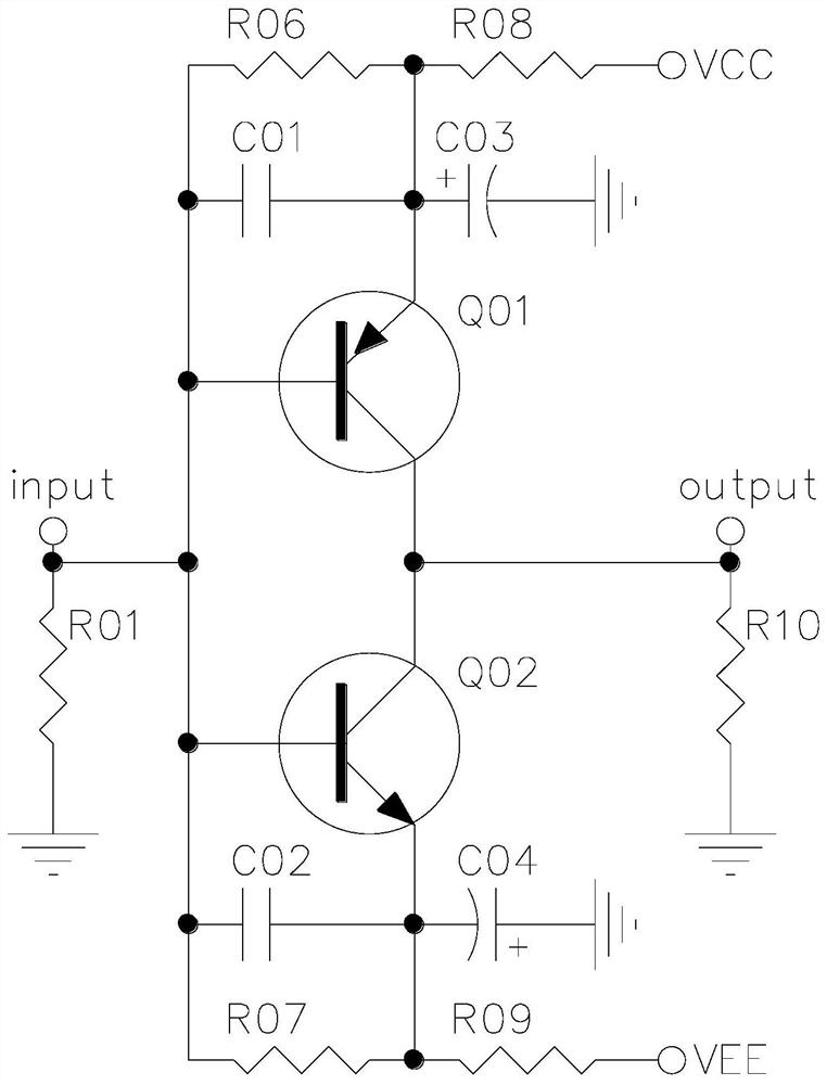
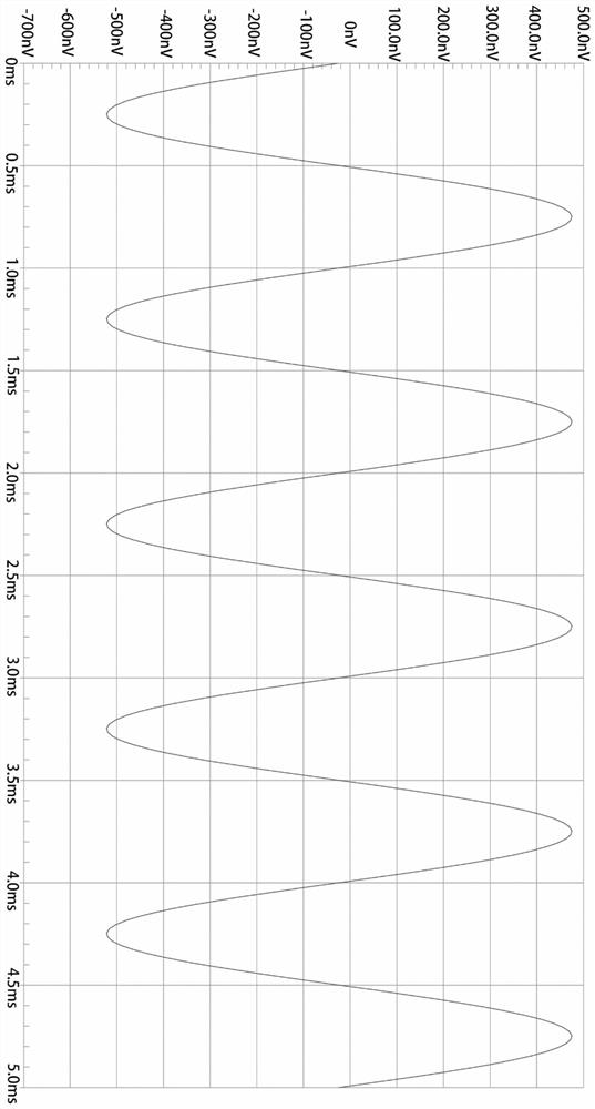
[0032] Such as Figure 1-Figure 2 As shown, the present invention discloses a moving coil cartridge amplifier circuit, which includes: a matching network, which is used to match the complementary transistor pair and the output impedance of the MC cartridge, and the matching network is connect...


PUM


Abstract

The invention discloses a moving-coil cartridge amplifying circuit, and the circuit comprises: a matching network electrically connected with a signal input end; low-frequency response filter circuits, wherein the low-frequency response filter circuits are symmetrically arranged and electrically connected with a positive power supply and a negative power supply respectively, and the low-frequency response filter circuits are electrically connected with the matching network; quiescent operating point circuits, wherein the quiescent operating point circuits are electrically connected with the low-frequency response filter circuit and the matching network, and the quiescent operating point circuits are symmetrically arranged and electrically connected with a positive power supply and a negative power supply respectively; an amplifying unit, wherein the amplifying unit comprises a first transistor and a second transistor, and the amplifying unit is electrically connected with the matching network, the low-frequency response filter circuit, the quiescent operating point circuit, a signal input end and a signal output end; and an output end load, wherein the output end load is electrically connected with the amplification unit and the signal output end. The advantages of low noise, low distortion, high signal-to-noise ratio, high dynamic range and wide frequency response are realized.

Description

technical field [0001] The invention relates to the field of amplifying circuit technical equipment, in particular to a moving-coil cartridge amplifying circuit. Background technique [0002] The existing MC phono amplifier circuit, in order to achieve better output effects, such as: low noise, low distortion, high signal-to-noise ratio, etc. Generally, a variety of modules or circuits are integrated together to improve the output effect, resulting in an overly complex overall circuit structure, which is cumbersome and time-consuming to debug. [0003] At the same time, the existing MC phono amplifier circuit often has a DC voltage at its input end, resulting in an increase in the DC offset of the circuit and increase in circuit distortion, thus making it impossible to obtain a better output effect. The adaptability and compatibility of external modules and circuits are poor, and re-adjustment and design are often required. [0004] Therefore, there is an urgent need for a...

Claims


Application Information

Patent Timeline
Patent Type & Authority Applications(China)
IPC IPC(8): H03F1/32H03F1/02H03F1/26H03F1/42H03F3/183
Inventor 温上凯
Owner 东莞凯韵科技有限公司
Why Eureka
Try Eureka