Eight-valve piston type dynamic flow measurement standard device and measurement method

A dynamic flow, valve piston technology, used in measuring devices, testing/calibrating devices, liquid/fluid solids measurement, etc. Effect

Active Publication Date: 2021-11-23
HEBEI UNIVERSITY
View PDF12 Cites 1 Cited by
  • Summary
  • Abstract
  • Description
  • Claims
  • Application Information

AI Technical Summary

Problems solved by technology

[0004] One of the purposes of the present invention is to provide an eight-valve piston type dynamic flow measurement standard device to solve the problem that the existing standard device is difficult to calibrate the flowmeter under dynamic flow

Method used


Image

  • Eight-valve piston type dynamic flow measurement standard device and measurement method
  • Eight-valve piston type dynamic flow measurement standard device and measurement method
  • Eight-valve piston type dynamic flow measurement standard device and measurement method

Examples


Embodiment 1

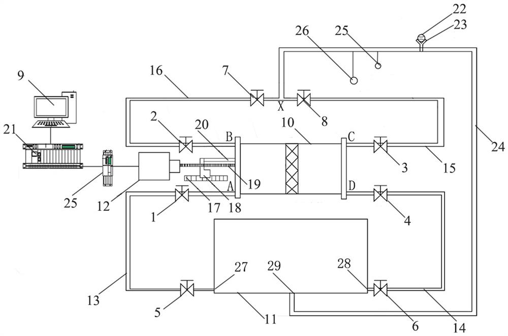
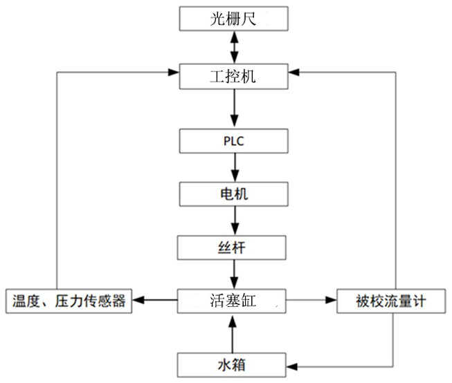
[0041] Such as figure 1 As shown, the present invention includes industrial computer 9, PLC21, servo drive, servo motor 12, leading screw 19, grating ruler 17, piston cylinder 10, water tank 11, pulsating flow pipeline network, calibration pipeline 24, the first valve 1, The second valve 2 , the third valve 3 , the fourth valve 4 , the fifth valve 5 , the sixth valve 6 , the seventh valve 7 , the eighth valve 8 , the pressure sensor 26 and the temperature sensor 25 . The pulsating flow pipeline network is connected between the piston cylinder 10, the water tank 11 and the calibration pipeline 24, and is used to make the pulsating flow always exist in the calibration pipeline 24 where the flowmeter 22 to be tested is located. The pulsating flow pipeline network includes a first water outlet pipe 15, a second water outlet pipe 16, a first water return pipe 13, a second water return pipe 14,

[0042] Among them, the industrial computer 9, the flowmeter 22 to be tested, the motor...

Embodiment 2

[0053] An eight-valve piston type dynamic flow measurement method, such as figure 1 and figure 2 shown, including the following steps:

[0054] a, prepare the eight-valve piston type dynamic flow metering standard device in embodiment 1, be provided with pressure sensor 26 and temperature sensor 25 on described calibration pipeline 24, flow through the liquid temperature and pressure information of tested flow meter 22 Real-time detection and acquisition.

[0055] b. The industrial computer 9 sends a pulse signal to the motor 12, and the motor 12 controls the nut 18 on the lead screw 19 to drive the piston rod 20 to move to the right. At the same time, the industrial computer 9 records and controls the displacement of the grating ruler 17 on the nut 18 in real time. The first valve 1, the third valve 3, the fifth valve 5 and the eighth valve 8 are opened, the second valve 2, the fourth valve 4, the sixth valve 6 and the seventh valve 7 are closed, and the extruded from the ...


PUM


Abstract

The invention provides an eight-valve piston type dynamic flow measurement standard device and a measurement method. The device comprises an industrial personal computer, a motor, a lead screw, a grating ruler, a piston cylinder, a water tank, a first pipeline, a second pipeline, a first water outlet pipe, a second water outlet pipe, a first water return pipe, a second water return pipe and a calibration pipeline. The industrial personal computer is electrically connected with a detected flowmeter, the motor, eight valves and the grating ruler, the displacement of the grating ruler and data of the detected flowmeter are obtained in real time, and rotation of the motor and opening and closing of the valves are controlled. The pulse displacement generated by the piston in the piston cylinder is controlled through the industrial personal computer, and the piston cylinder, the water tank, the first pipeline, the second pipeline, the first water outlet pipe, the second water outlet pipe, the first water return pipe, the second water return pipe and the calibration pipeline are arranged, so that pulsating flow always exists in the calibration pipeline where the detected flowmeter is located, the pulsating flow amplitude and frequency are adjusted in real time, the precision of the detected flowmeter under a dynamic flow signal is detected, and the instantaneous liquid volume flow value can be displayed in real time.

Description

technical field [0001] The invention relates to the technical field of mechanical design and flow detection, in particular to an eight-valve piston type dynamic flow measurement standard device and a measurement method. Background technique [0002] Existing piston-type devices are mostly used for static flow standard devices. A piston-type water meter verification device (patent number: 202021284357.4) This utility model passes through the set sump, screen, water baffle, water pump and conduit, and then cooperates with the water pump The conduit recycles the collected water, which greatly saves water resources. When using the support rod, flow detector, chute, slider and cylinder, it is suitable for water meters of different sizes for verification, which is more practical and suitable for Widely promoted and used; an online measurement method for the effective volume of the piston cylinder of a piston-type gas flow standard device (patent number: 201911195783.2). During the...

Claims


Application Information

Patent Timeline
Patent Type & Authority Applications(China)
IPC IPC(8): G01F25/00
CPCY02A20/00
Inventor 方立德刘宏伟郭素娜王帆
Owner HEBEI UNIVERSITY
Why Eureka
Try Eureka