Hydraulic control driving system

A drive system and hydraulic technology, applied in the direction of fluid pressure actuation system components, fluid pressure actuation devices, servo motors, etc., can solve the problem of limited flow of servo valves, failure of cylinders or hydraulic motors to meet speed requirements, and failure to meet actual needs, etc. problem, to achieve the effect of meeting the requirements of precision and speed

Pending Publication Date: 2021-11-16
WUHAN MARINE MACHINERY PLANT
View PDF0 Cites 0 Cited by
  • Summary
  • Abstract
  • Description
  • Claims
  • Application Information

AI Technical Summary

Problems solved by technology

[0004] However, when the system not only requires high control precision, but also requires the movement speed to be reached within a limited time, due to the limited flow of the servo valve, the selected servo valve cannot make the oil cylinder or hydraulic motor output within a limited time even if it is output according to the maximum flow. Meet the speed requirements, and ultimately cannot meet the actual needs

Method used


Image

  • Hydraulic control driving system

Examples


Embodiment Construction

[0042] In order to make the purpose, technical solution and advantages of the present disclosure clearer, the implementation manners of the present disclosure will be further described in detail below in conjunction with the accompanying drawings.

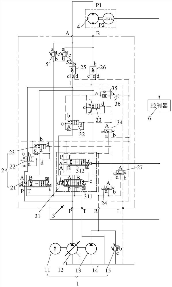
[0043] The embodiment of the present disclosure provides a hydraulic control drive system, such as figure 1 As shown, the hydraulic control drive system includes a power input unit 1 , a first control unit 2 , a second control unit 3 and an actuator 4 . The first control unit 2 includes a first servo valve 21, the oil inlet P of the first servo valve 21 communicates with the oil outlet of the power input unit 1, and the oil return port T of the first servo valve 21 communicates with the return port of the power input unit 1. The oil ports are connected, the first oil port A of the first servo valve 21 communicates with the first oil port P1 of the actuator 4 , and the second oil port B of the first servo valve 21 communicates with ...


PUM


Abstract

The invention provides a hydraulic control driving system, and belongs to the field of mechanical hydraulic control. The hydraulic control driving system comprises a power input unit, a first control unit, a second control unit and an execution element. The power input unit comprises a motor, a main pump, a control pump and an oil tank, the motor is used for driving the main pump and the control pump, an oil inlet of the main pump communicates with the oil tank, and an oil inlet of the control pump communicates with the oil tank; and the first control unit comprises a first servo valve, an oil inlet of the first servo valve communicates with an oil outlet of the main pump, an oil return opening of the first servo valve communicates with the oil tank, a first oil opening of the first servo valve communicates with an oil inlet of the execution element, and a second oil port of the first servo valve communicates with an oil outlet of the execution element. The driving system is hydraulically controlled, and the requirements for high-precision position control and high-precision and large-interval speed control can be met at the same time.

Description

technical field [0001] The disclosure belongs to the field of mechanical hydraulic control, in particular to a hydraulic control driving system. Background technique [0002] The hydraulic control drive system is a common power-driven device. Its function is to convert hydraulic energy into mechanical energy. By inputting the flow and pressure of the fluid in the system, it finally outputs linear motion (driving cylinder linear motion) or output rotational motion ( Drive the hydraulic motor to rotate). [0003] In related technologies, a hydraulic control drive system generally uses a small flow, high-precision servo valve combined with other valves to control an oil cylinder or a hydraulic motor, so that the control precision of the system is high. [0004] However, when the system not only requires high control precision, but also requires the movement speed to be reached within a limited time, due to the limited flow of the servo valve, the selected servo valve cannot ma...

Claims


Application Information

Patent Timeline
IPC IPC(8): F15B21/08F15B11/042F15B11/08F15B13/04
CPCF15B21/087F15B11/0426F15B11/08F15B13/0401
Inventor 汤波方敏叶建刘琥铖刘杰
Owner WUHAN MARINE MACHINERY PLANT
Why Eureka
Try Eureka