Disassembling and assembling tool for valve seats of cone valves of diaphragm pump

A technology for disassembling and assembling tools and diaphragm pumps, which is applied in the manufacture of tools and hand-held tools, etc., which can solve the problems of low efficiency, time-consuming and laborious, etc., and achieve the effects of convenient operation, reduced strength and simple structure

Pending Publication Date: 2021-11-12
安徽马钢矿业资源集团姑山矿业有限公司 +1
View PDF0 Cites 0 Cited by
  • Summary
  • Abstract
  • Description
  • Claims
  • Application Information

AI Technical Summary

Problems solved by technology

[0004] Aiming at the defects and deficiencies in the prior art, the present invention provides a disassembly tool for the valve seat of the diaphragm pump cone valve. The present invention is simple in structure and convenient in operation. Under certain circumstances, it can quickly and effectively disassemble and assemble the valve seat of the diaphragm pump cone valve, which greatly reduces the intensity of equipment maintenance work, saves time and effort, and provides an efficient auxiliary tool for equipment maintenance and disassembly to meet production needs. It solves the problems of low efficiency, time-consuming and labor-intensive dismantling and replacement of the inlet and outlet cone valve seats of the existing reciprocating hydraulic diaphragm pump, and has good promotion and application value

Method used


Image

  • Disassembling and assembling tool for valve seats of cone valves of diaphragm pump
  • Disassembling and assembling tool for valve seats of cone valves of diaphragm pump
  • Disassembling and assembling tool for valve seats of cone valves of diaphragm pump

Examples


Embodiment 1

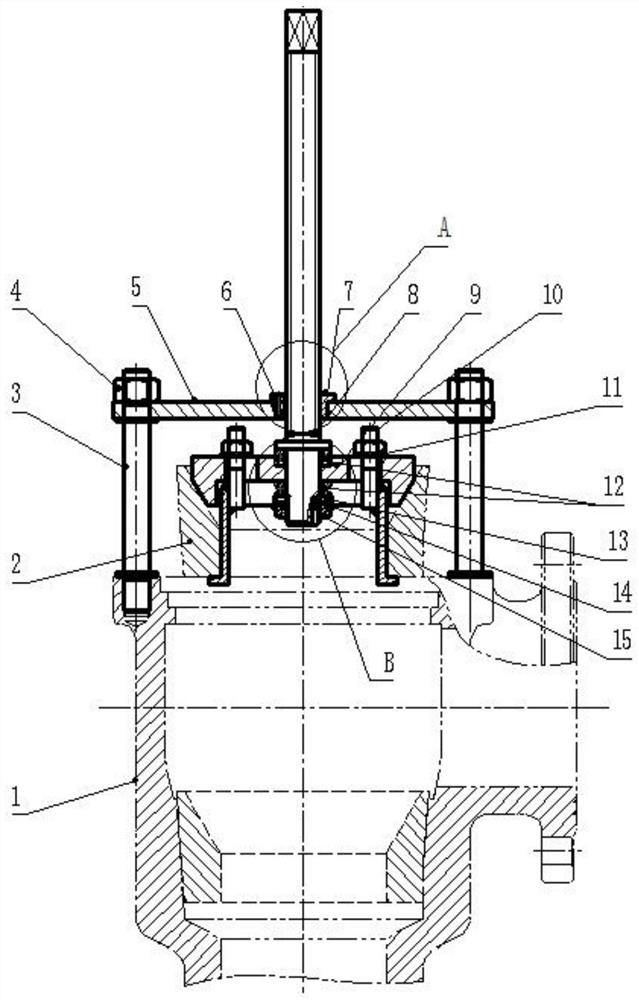
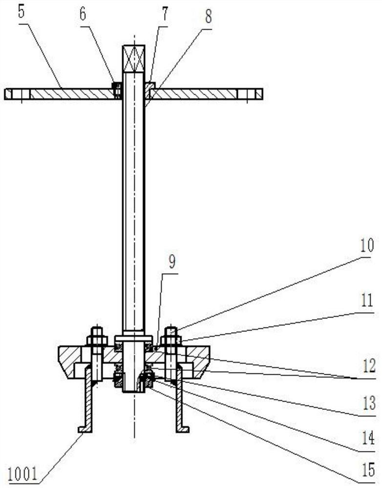
[0027] from Figure 1-3 It can be seen that the assembly and disassembly tool for a cone valve seat of a diaphragm pump in this embodiment includes a beam frame 5, a screw rod 8 is installed in the middle of the beam frame 5, and one end of the screw rod 8 runs through the beam frame 5 and is connected with a valve. Seat pressing block 9, the surface of valve seat pressing block 9 is provided with pull rod 10 at intervals, one side end of pull rod 10 is provided with pull rod nut 11, and pull rod 10 is locked with valve seat pressing block 9 through pull rod nut 11.

[0028] The bottom of the beam frame 5 is connected with a cone valve box 1, and the surface of the cone valve box 1 is provided with a valve seat 2.

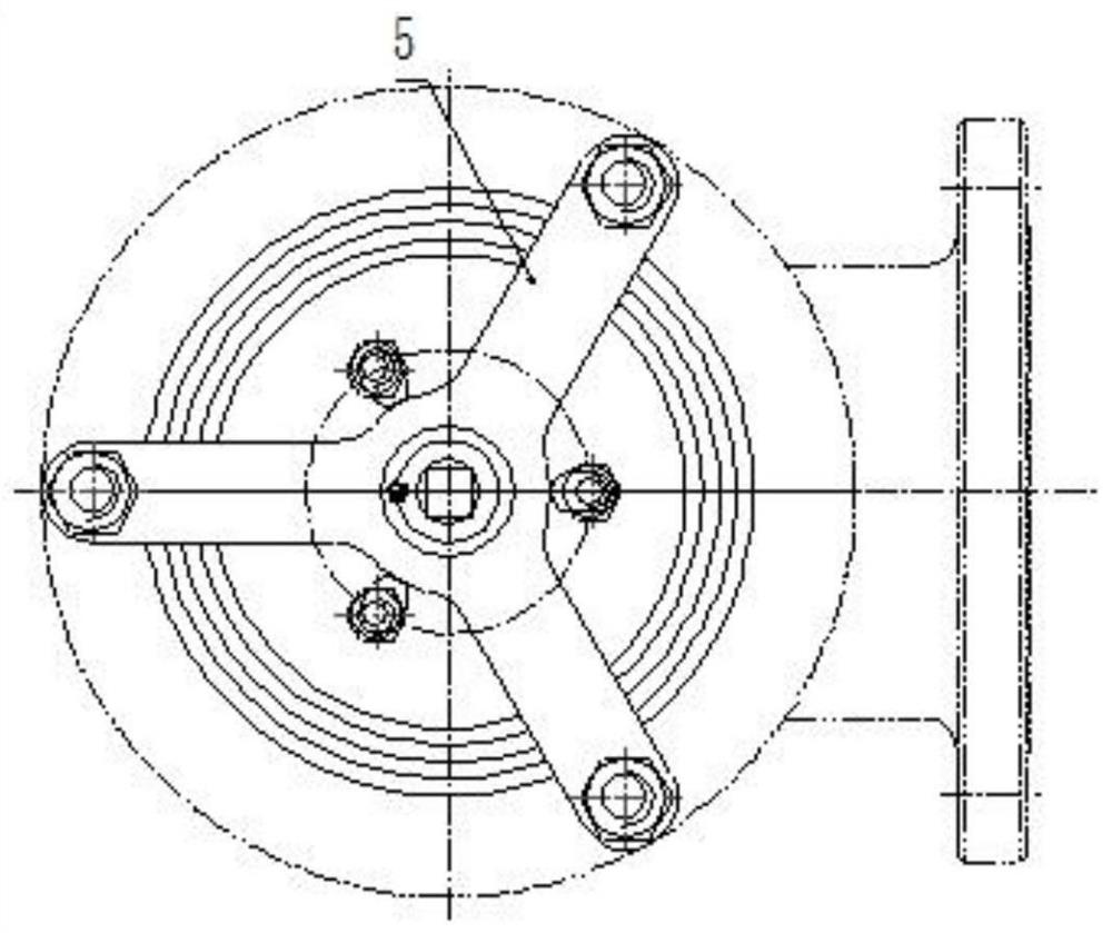
[0029] The beam frame 5 is in the shape of a trident frame, and is made of steel plate. The central axis of the beam frame 5 is provided with screw holes, and the trident ends of the beam frame 5 are evenly arranged with bolt holes. The column bolts 3 are installed...


PUM


Abstract

The invention discloses a disassembling and assembling tool for valve seats of cone valves of a diaphragm pump, and belongs to the technical field of overhaul for diaphragm pumps. The disassembling and assembling tool for the valve seats of the cone valves of the diaphragm pump comprises a beam frame, wherein a lead screw is installed at the middle part of the beam frame, one end of the lead screw penetrates through the beam frame and is connected with a valve seat pressing block, pull rods are arranged on the surface of the valve seat pressing block at intervals, pull rod nuts are arranged at the ends of one sides of the pull rods, and the pull rods and the valve seat pressing block are locked through the pull rod nuts. The disassembling and assembling tool for the valve seats of the cone valves of the diaphragm pump is simple in structure and convenient to operate, and the valve seats of the cone valves of the diaphragm pump can be quickly and effectively disassembled and assembled with the help of use of the tool under the condition that manual repeated adjustment depending on experience is not needed, so that the intensity of equipment overhaul work is greatly relieved, and the time and labor are saved; and in order to meet the production requirements, an efficient auxiliary tool for maintenance, disassembling and assembling for equipment is provided, the problems of low efficiency, time and labor waste and the like in disassembling, inspection and replacement processes for valve seats of an inlet cone valve and an outlet cone valve of an existing reciprocating hydraulic diaphragm pump are solved, and good popularization and application values are achieved.

Description

technical field [0001] The invention relates to the technical field of diaphragm pump maintenance, and more specifically relates to a high-pressure dry oil air control valve. Background technique [0002] In the metallurgical and mining industry, such as reciprocating hydraulic diaphragm pumps and other equipment used for long-distance transportation, in the process of beneficiation, due to the wear and tear of the fine tailings slurry and long-distance high-pressure transportation, the components of the diaphragm pump —The wear and tear of the spool and taper sleeve is relatively serious. The components that control the entry and exit of mineral materials are generally composed of a cone valve box, a valve core, a rubber seal and a valve seat. Diaphragm pump conveying water or material is generally completed by the alternating action of inlet valve and outlet valve. Each conveying requires the opening and closing of the inlet and outlet valves, coupled with the influence o...

Claims


Application Information

Patent Timeline
Patent Type & Authority Applications(China)
IPC IPC(8): B25B27/02
CPCB25B27/023
Inventor 李明军钱士湖薛世润杨松付王金行梁朝杰郑思冉陆虎伍开峰
Owner 安徽马钢矿业资源集团姑山矿业有限公司
Why Eureka
Try Eureka