Brake pad disassembling device

A technology of brake pads and movement, applied in the direction of brake parts, manufacturing tools, hand-held tools, etc., can solve problems such as difficulty in disassembling the brake pads

Pending Publication Date: 2020-10-20
BEIJING TIANRENDAOHE NEW MATERIAL CO LTD
View PDF0 Cites 0 Cited by
  • Summary
  • Abstract
  • Description
  • Claims
  • Application Information

AI Technical Summary

Problems solved by technology

[0004] Therefore, the technical problem to be solved by the present invention is to overcome the lack of a brake pad dismantling devic...

Method used


Image

  • Brake pad disassembling device
  • Brake pad disassembling device
  • Brake pad disassembling device

Examples


Embodiment 1

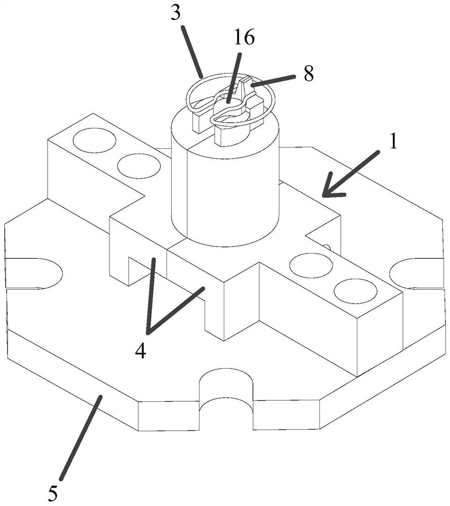
[0049] A brake pad dismantling device is described, such as figure 1 shown, including:

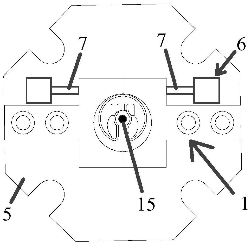
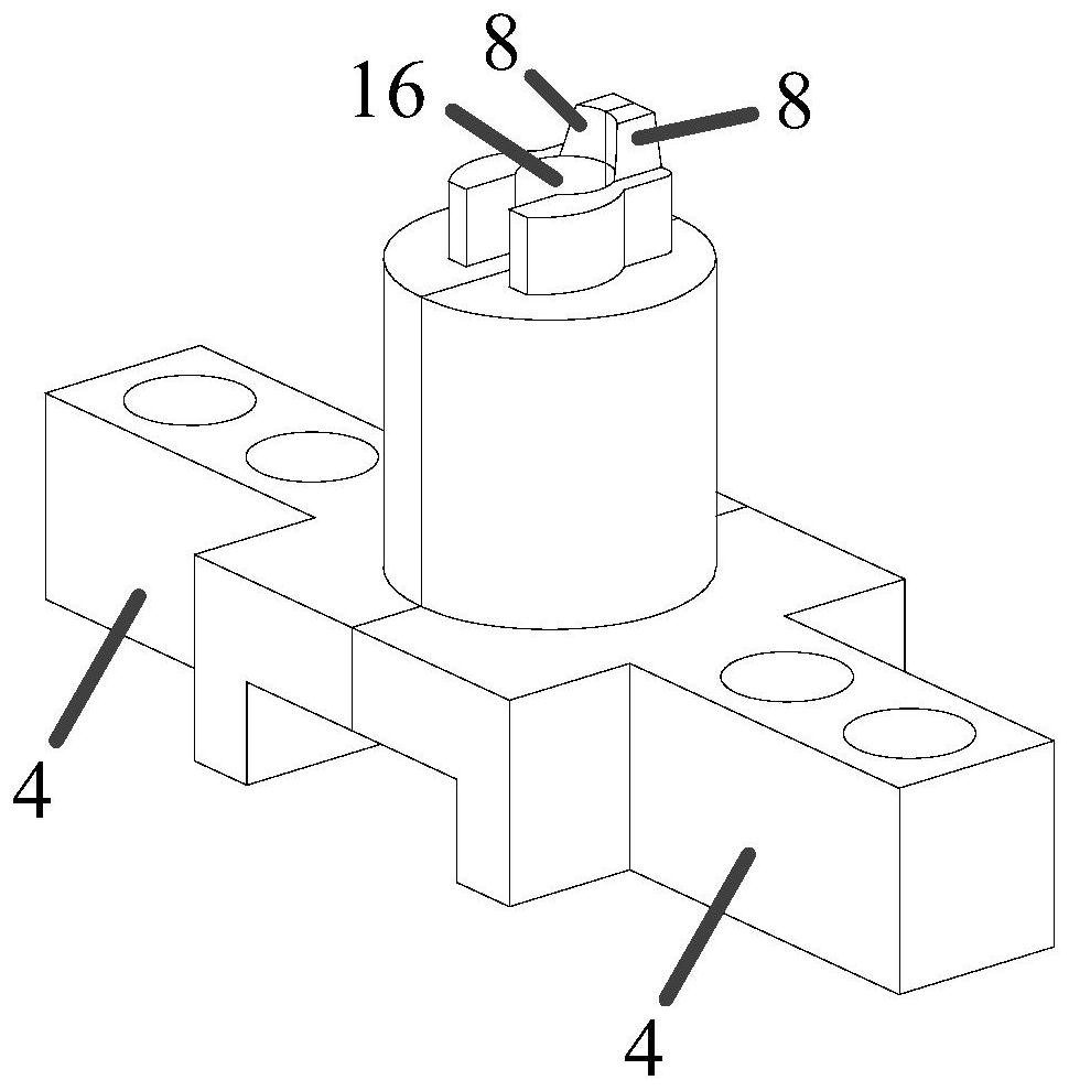
[0050] The opening and closing claw 1, the opening and closing claw 1 is adapted to the shape of the clip spring 3 of the brake pad 2, and the opening and closing claw 1 includes oppositely arranged and driven to move toward or away from each other. Clamping part 4; such as Figure 4 and Figure 5 As shown, in this example as Image 6 As shown, the snap ring 3 includes an outer ring 9, an inner ring 10, and two extensions 11 located on the inner ring 10 and oppositely arranged; as figure 2 and image 3 As shown, the engaging portion 4 is connected to the extension portion 11 to drive the two extension portions 11 away from each other. Through the above-mentioned opening and closing claw 1, it can be precisely connected with the brake pad 2 and its clip spring 3, and the clip spring 3 will be moved during the opposite movement of the two oppositely arranged snap-in parts 4 that make u...


PUM


Abstract

The invention provides a brake pad disassembling device. The brake pad disassembling device comprises an opening and closing clamping jaw, wherein the opening and closing clamping jaw is matched witha clamping spring of a brake pad in shape, and the opening and closing clamping jaw comprises clamping parts which are oppositely arranged and are driven to move towards each other or away from each other. According to the brake pad disassembling device, the clamping spring can be rapidly and effectively disassembled from a steel backing through the opening and closing clamping jaw, so that the problem that the brake pad is difficult to disassemble due to the fact that a brake pad disassembling device is lacked in the prior art is solved.

Description

technical field [0001] The invention relates to the technical field of brake devices, in particular to a brake pad disassembly device. Background technique [0002] At present, the braking of high-speed trains mainly relies on the mutual friction between brake pads and brake discs. As the speed of the train continues to increase, the braking load is increasing, and the requirements for the braking performance of the brake pads are also getting higher and higher. replace. In order to save costs and respond to the national green and environmental protection policy, the steel back of the brake pad can be reused if it meets the relevant quality requirements, which requires the brake pad to be disassembled. [0003] In the prior art, the brake pads are disassembled manually to realize the dismantling work of the brake pads. However, during the dismantling process of the brake pads, due to the influence of special structural components such as the circlip and the triangular bra...

Claims


Application Information

Patent Timeline
IPC IPC(8): B25B27/30F16D65/02
CPCB25B27/302F16D65/02
Inventor 龙波赵旭孙志远石一婷骆亚涛赵尚节
Owner BEIJING TIANRENDAOHE NEW MATERIAL CO LTD
Why Eureka
Try Eureka