
Porous heat dissipation heat sink and manufacturing method thereof

A technology of heat dissipation heat sink and manufacturing method, which is applied in the direction of laser components, semiconductor lasers, electrical components, etc., can solve the problems of unsuitable chip heat dissipation heat sink, large pore size, and overall size limitation, so as to achieve enhanced bonding force, Effect of reducing volume and preventing oxidation

Active Publication Date: 2021-11-09
FOSHAN HUAZHI ADVANCED MATERIALS CO LTD
View PDF13 Cites 0 Cited by
  • Summary
  • Abstract
  • Description
  • Claims
  • Application Information

AI Technical Summary

Problems solved by technology

The internal channel of the laser heat sink is made of plates, and the number and size of the ribs are usually increased to increase the contact area between the coolant and the radiator, thereby achieving enhanced heat dissipation, but limited by the overall size of the heat sink, the heat dissipation effect is limited
[0004] Porous heat sinks have the advantages of high heat dissipation efficiency and uniform heat dissipation, but the heat dissipation channels of common porous heat sinks are made of foamed metal, and the pores of the formed porous structure have a large pore size, which is not suitable for small-sized chips. heat sink

Method used


Image

  • Porous heat dissipation heat sink and manufacturing method thereof
  • Porous heat dissipation heat sink and manufacturing method thereof
  • Porous heat dissipation heat sink and manufacturing method thereof

Examples


Embodiment 1

[0077] The method of manufacturing the porous heat sink of the following embodiment includes step one to fourth steps as follows.

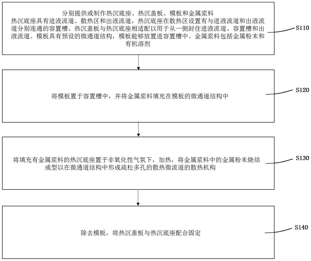
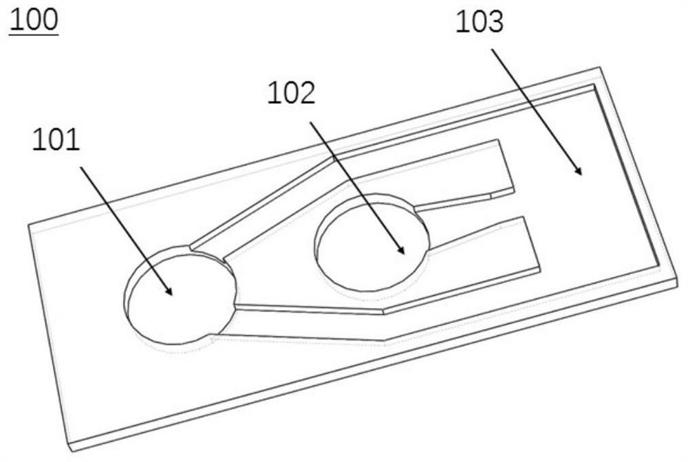
[0078] Step 1: figure 2 with image 3 As shown, a thermal sink base 100, a thermal sink 400, a template 200, and a metal slurry 300 are provided, respectively.

[0079] Among them, the heat sink base 100 has an in-liquid flow channel 102, the heat dissipation zone, and the liquid flow channel 101, and the heat sink base 100 is provided with a receiving groove 103 that communicates with the in-liquid flow channel 102 and the liquid flow channel 101, respectively. . The heat sink 400 is adapted to the heat sink base 100 for sealing the liquid flow channel 102, the accommodating groove 103, and the liquid flow channel 101 from one side. The template 200 has a preset microchannel structure, and the template 200 is fitted to the accommodating groove 103. The metal slurry 300 includes a metal powder, a reducing agent, an organic solvent, a thickener.

[0080...

Embodiment 2

[0091] The method for producing the porous heat sink of Example 2 is substantially the same as in Example 1, and the different places in the configuration of a metal slurry.

[0092] The configuration method of the metal slurry 300 is: a copper powder of 80 μm and a particle diameter of 30 μm and a particle diameter of 30 μm in mass ratio 1: 1, mixed with a propionate containing lactic acid, then adding thickener ethylcellulose. , Stir evenly and form a viscosity of 150 Pa. The metal slurry of S is 300, wherein the copper powder, lactic acid, propylene glycol, and ethylcellulose are 23%, 10%, 60%, 7%;

[0093] The porosity of the heat dissipation mechanism for preparing the obtained porous cooling heat sink is 53.2%.


PUM

PropertyMeasurementUnit
widthaaaaaaaaaa
lengthaaaaaaaaaa
thicknessaaaaaaaaaa

Abstract

The invention relates to a manufacturing method of a heat dissipation heat sink. The manufacturing method comprises the following steps that a heat sink base, a heat sink cover plate, a template and metal slurry arerespectively provided or manufactured; the heat sink base is provided with an accommodating groove in the heat dissipation area; the template is provided with a preset micro-channel structure, and the template can be placed in the accommodating groove; the metal slurry comprises metal powder and an organic solvent; the template is placed in the accommodating groove, and the micro-channel structure of the template is filled with the metal slurry; the heat sink base filled with the metal slurry is placed in a non-oxidizing atmosphere and heated, and metal powder in the metal slurry is sintered and formed so that a loose and porous heat dissipation mechanism can be formed in the micro-channel structure; and the template is removed, and the heat sink cover plate and the heat sink base are fixed in a matched mode.

Description

Technical field [0001] The present invention relates to the field of high-power chip heat dissipation, and more particularly to a porous heat sink and a method of manufacturing the same. Background technique [0002] As the chip is getting smaller and smaller, the technique evolve is increasing, and the requirements for heat dissipation are also increasing. Taking the laser chip as an example, with the continuous improvement of the laser power, the laser bar strip is a basic composition unit of the laser array and also requires more heat dissipation performance. Half-level power to be converted to calorify, if the laser heat dissipation capacity is increased, and the light source wavelength of the laser bar will be drifted, and the light output power will fall or have saturated More seriously further shorten the life of the laser. [0003] The currently high-power laser heat sink mainly includes a macro channel heat sink and micro-channel heat sink, and the two heat sinks are tak...

Claims


Application Information

Patent Timeline
Patent Type & Authority Applications(China)
IPC IPC(8): H01S5/024
CPCH01S5/02423
Inventor 王郑陈俊凯陈铭汉
Owner FOSHAN HUAZHI ADVANCED MATERIALS CO LTD
Learn More