Eureka AIR delivers breakthrough ideas for toughest innovation challenges, trusted by R&D personnel around the world.

LED lamp and manufacturing method thereof

A technology of LED lights and manufacturing methods, which is applied in the field of lighting, can solve the problems of difficult light spots, high cost of LED lights, and high production costs, and achieve the effects of simple treatment of light spots, improved light output efficiency, and reduced production costs

Pending Publication Date: 2021-11-09
NINGBO SUNPU OPTO SEMICON
View PDF0 Cites 1 Cited by
  • Summary
  • Abstract
  • Description
  • Claims
  • Application Information

AI Technical Summary

Problems solved by technology

These methods all have various disadvantages. In the first method, the ineffective phosphor area is large, and there is a phosphor layer between adjacent LED chips, and the boundary of the light spot is not obvious, which makes it difficult to deal with the light spot at the application end; In the second method, phosphor glue will seep into the connection between the steel mesh and the substrate, resulting in poor appearance and uneven color temperature of the LED lamp. Moreover, the steel mesh is a consumable material, which makes the production cost high. At the same time, manual alignment of the steel mesh is required, which is accurate In the third way, adhesives are needed to bond between the fluorescent sheet patch and the LED chip, which will reduce the light output efficiency of the LED lamp, and the production cost and purchase cost of the fluorescent sheet patch are high, resulting in high cost of the LED lamp. , and the process of pasting the fluorescent sheet on the LED chip is complicated, which requires high equipment precision and the color temperature change is relatively rigid

Method used


Image

  • LED lamp and manufacturing method thereof
  • LED lamp and manufacturing method thereof
  • LED lamp and manufacturing method thereof

Examples


Embodiment Construction

[0041] In order to enable those skilled in the art to better understand the solution of the present application, the present application will be further described in detail below in conjunction with the drawings and specific implementation methods. Apparently, the described embodiments are only some of the embodiments of this application, not all of them. Based on the embodiments in this application, all other embodiments obtained by persons of ordinary skill in the art without making creative efforts belong to the scope of protection of this application.

[0042] In the following description, a lot of specific details are set forth in order to fully understand the present invention, but the present invention can also be implemented in other ways different from those described here, and those skilled in the art can do without departing from the connotation of the present invention. By analogy, the present invention is therefore not limited to the specific examples disclosed be...


PUM


Abstract

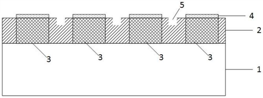
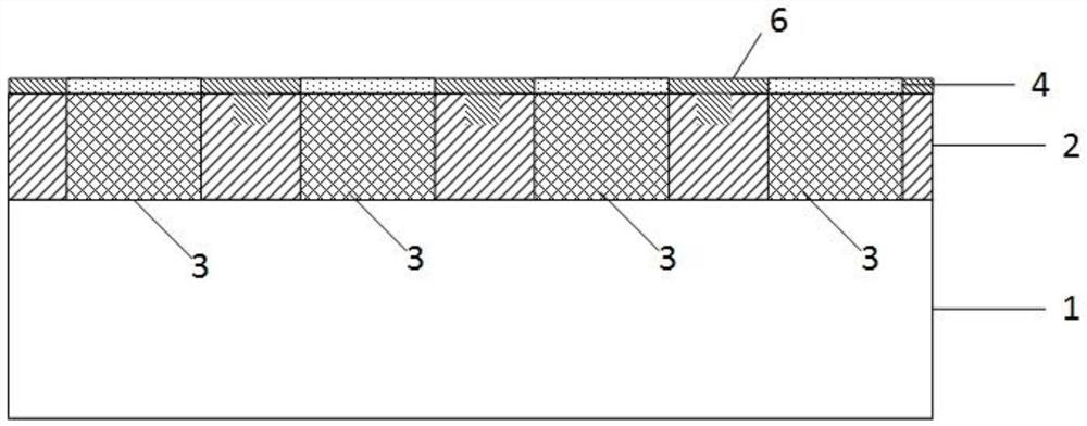
The invention discloses an LED lamp. The LED lamp comprises a substrate; a plurality of LED chips which are arranged on the substrate and are electrically connected with the substrate; a fluorescent powder layer which is arranged on the upper surfaces of the LED chips; and a first white wall glue part which is arranged on the substrate and around the LED chips, and is provided with grooves distributed between the adjacent LED chips. The fluorescent powder layer is only arranged on the upper surfaces of the LED chips, so that invalid fluorescent powder areas are greatly reduced. The first white wall glue part is provided with the grooves between the adjacent LED chips, that is, there is no fluorescent powder layer between the adjacent LED chips, so that the boundaries of the light-emitting areas of the LED lamps are very obvious, and light spots are optimized. According to the LED lamp, the use of a fluorescent sheet patch is avoided, an adhesive and a steel mesh are not needed between the LED chips and the fluorescent powder layer, the manufacturing cost is reduced, the light emitting efficiency is improved, meanwhile, fluorescent glue is prevented from overflowing, and the attractiveness of the LED lamp is improved. The invention further provides a manufacturing method with the advantages.

Description

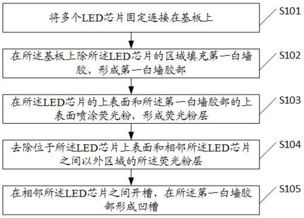
technical field [0001] The present application relates to the technical field of lighting, in particular to an LED lamp and a manufacturing method thereof. Background technique [0002] LED (Light-Emitting Diode, light-emitting diode) is made of compounds containing gallium (Ga), arsenic (As), phosphorus (P), nitrogen (N), etc. It is a semiconductor component and is widely used in various indications, Display, decoration, backlight, general lighting and urban night scenes and other fields. [0003] During the production process, the LED chip needs to be covered with a phosphor layer. Currently, there are several methods: the first method, the overall spraying, the phosphor layer not only covers the LED chip, but also covers the area corresponding to the substrate other than the LED chip; the second method 1. Use steel mesh to block the area other than the LED chip, and spray phosphor powder on the LED chip area; the third method is to use a fluorescent sheet patch to stick ...

Claims


Application Information

Patent Timeline
Patent Type & Authority Applications(China)
IPC IPC(8): H01L33/50H01L33/54H01L25/075
CPCH01L33/50H01L33/54H01L25/0753H01L2933/0041H01L2933/005
Inventor 张耀华王国君宓超杜元宝朱小清陈复生
Owner NINGBO SUNPU OPTO SEMICON
Why Eureka
Eureka Blog
Learn More