
Patch type fuse and batch manufacturing method thereof

A fuse and chip-type technology, which is applied in the field of fuses with low-temperature rise performance and batch manufacturing, can solve the problems of terminal electrodes and fuses falling off, deformation of insulating shells, and difficulty in heat dissipation, etc., to improve long-term use reliability , The heat dissipation area is increased, and there is no effect of heat accumulation

Pending Publication Date: 2021-11-09
NANJING SART SCI & TECH DEV
View PDF4 Cites 0 Cited by
  • Summary
  • Abstract
  • Description
  • Claims
  • Application Information

AI Technical Summary

Problems solved by technology

The advantage of this structure is mainly to reduce the contact resistance between the metal melt and the end electrodes, but the disadvantages are also obvious. Because the silicone resin is at the bottom of the product, it is difficult to dissipate heat, and it is in direct contact with the metal sheet of the fuse, which is easy to Cause heat accumulation, and its sealing resin will age with the increase of product use time and temperature, which will cause the end electrodes and fuses to fall off
Chinese patent 201320839953.8 uses a ceramic material bottom cover and high thermal conductivity adhesive as the sealing layer at the opening end of the insulating shell, but the patent still clearly points out that the high temperature generated by the fuse will quickly heat up the ceramic material and eventually cause the temperature of the ceramic material to be higher than that of the metal The temperature of the melting point, so that the fuse body will fall off the main board of the electronic device
Considering this potential failure, Chinese patent 201680085101.0 designed a base with complex structure to replace this sealing layer. The production process of the product is relatively complicated, and the material dimensional accuracy is very high; The inner shell of the bump and the outer shell with grooves are connected by a snap-fit ​​insulating shell structure, but because the outer shell has a certain elasticity, it is convenient to press the groove of the outer shell into the bump of the inner shell Therefore, the material of the shell can only be plastic or bakelite, which has insufficient heat resistance, and the insulating shell of the product may be deformed after reflow soldering

Method used


Image

  • Patch type fuse and batch manufacturing method thereof
  • Patch type fuse and batch manufacturing method thereof
  • Patch type fuse and batch manufacturing method thereof

Examples


Embodiment 1

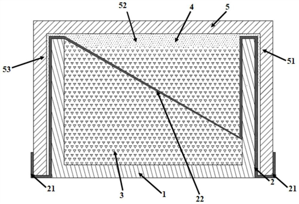
[0036] Such as figure 1As shown, the chip fuse includes an insulating inner shell 1 , an insulating outer shell 5 , a metal sheet 2 , an arc-extinguishing material 3 , and a high-temperature thermoplastic resin 4 . The insulating inner shell 1 is a rectangular parallelepiped shell with four first side walls and a bottom surface, the insulating shell 5 is a rectangular parallelepiped shell with four second side walls and a top face, and the edge shell 5 is covered by the insulating inner shell 1 Peripherally, the first side wall of the insulating inner shell 1 forms a cavity together with the top surface and the bottom surface. The arc extinguishing material 3 fills the cavity of the insulating inner shell 1 . There are gaps 51 and 53 between the upper half of the first side wall and the upper half of the second side wall, and there is a gap 52 between the inner side of the top surface of the insulating shell 5 and the upper surface of the arc-extinguishing material 3 filled i...

Embodiment 2

[0049] combine figure 1 and as Figure 6 The metal sheet 2 includes two end electrodes 21 and a fuse 22 integrally formed, wherein the fuse 22 is distributed in the inner cavity of the insulating inner shell 1 and is inclined relative to the bottom surface of the insulating inner shell 1. A circular hole is set in the middle of the body 22 , one end of the fuse body 22 abuts against the wall opening inside the first side wall, and the other end abuts against the corresponding inner side of the first side wall. One end of the fuse 22 is bent and extended to extend out an extension portion 23, which extends from the wall opening of the first side wall, extends downward against the outside of the first side wall, and protrudes to the bottom edge of the second side wall, The protruding end electrode 21 is parallel to the outer side of the second side wall; the other end of the fuse 22 is bent and extended out of the extension part 23, and the extension part sticks to the inner si...

Embodiment 3

[0051] The structures of the insulating inner shell 1 and the insulating outer shell 5 in the chip type fuse of the present invention are as follows: Figure 7 shown. Figure 7 (a) is the basic structure of the insulating case 5 , and the insulating case 5 includes four side walls, 51 , 52 , 53 , 54 in sequence, and a top surface 55 . Figure 7 (b) is the basic structure of the insulating inner shell 1. The insulating inner shell 1 includes four side walls, which are 11, 12, 13, 14 in sequence, and a bottom surface 15. The inner cavity of the insulating inner shell 1 is a cylinder 15. The distance between the opposite two side walls in the insulating inner shell 1, such as the distance between 11 and 13 and the distance between 12 and 14, is smaller than the distance between the corresponding two side walls in the insulating shell 5, that is, the above-mentioned distance is less than The distance between 51 and 53 and the distance between 52 and 54 are to ensure that the insu...


PUM


Abstract

The invention discloses a patch type fuse which comprises an insulating inner shell, an insulating outer shell and a metal sheet. The insulating inner shell is provided with a first side wall and a bottom surface, the insulating outer shell is provided with a second side wall and a top surface, the insulating outer shell covers the periphery of the insulating inner shell, the first side wall, the top surface and the bottom surface jointly define an inner cavity, and the metal sheet comprises a fuse link located in the inner cavity and extension parts bent and extending from the two sides of the fuse link. The extension parts extend out from the positions between the first side walls and the corresponding second side walls to form end electrodes, and the high-temperature thermoplastic resin is filled in the inner side of the top face and the positions between the first side walls and the second side walls and enables the insulating inner shell and the insulating outer shell to be fixedly connected. And the high-temperature thermoplastic resin wraps the extension part of the metal sheet located at the top of the first side wall and the extension part located between the first side wall and the second side wall. The bonding surfaces between the insulating inner shell and the insulating outer shell are placed on the top surface and the side surface of the product and have a good heat dissipation relationship with the external environment, so that the fuse has good low temperature rise performance.

Description

technical field [0001] The invention relates to a chip type fuse, in particular to a fuse with low-temperature rise performance and a batch manufacturing method. Background technique [0002] With the development of industries such as power batteries and small energy storage tools, there is an increasing demand for high-current surface-mount fuse products, and its temperature rise characteristics are particularly important. Considering the structural design of the product itself, the traditional shell-shaped fuse products use leaded solder to form an electrical connection between the internal metal melt and the external end cap through high-temperature melting welding and similar methods, and with the product itself As the rated current is getting higher and higher, the structure and main performance indicators of products obtained by welding technology, such as the limitations of temperature rise, are gradually becoming prominent, and a new product design is required to mee...

Claims


Application Information

Patent Timeline
Patent Type & Authority Applications(China)
IPC IPC(8): H01H85/17H01H85/08H01H85/175H01H85/18H01H69/02
CPCH01H85/17H01H85/08H01H85/175H01H85/18H01H69/02H01H2069/025
Inventor 刘明龙
Owner NANJING SART SCI & TECH DEV
Learn More