A transition function hydraulic valve

A hydraulic valve and functional technology, which is applied in the direction of mechanical equipment, fluid pressure actuators, servo motor components, etc., can solve the problem of large impact on the working oil port, achieve smooth movement, ensure positional accuracy, and reduce noise.

Active Publication Date: 2022-02-22
JIANGSU HENGLI HYDRAULIC TECH CO LTD
View PDF7 Cites 0 Cited by
  • Summary
  • Abstract
  • Description
  • Claims
  • Application Information

AI Technical Summary

Problems solved by technology

[0003] In order to solve the problem in the prior art that the working oil port suffers a relatively large impact when reversing, the present invention provides a transitional function hydraulic valve that reduces the impact on the working oil port when reversing

Method used


Image

  • A transition function hydraulic valve
  • A transition function hydraulic valve
  • A transition function hydraulic valve

Examples


Embodiment 1

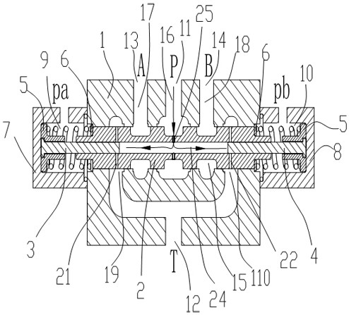
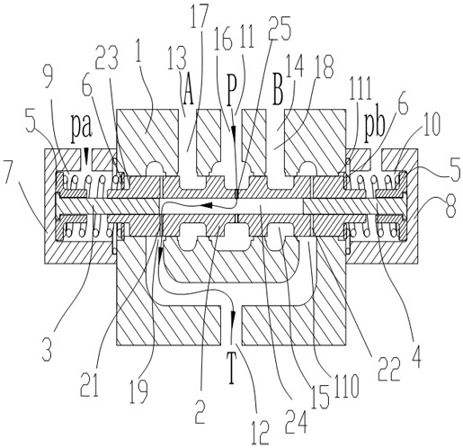
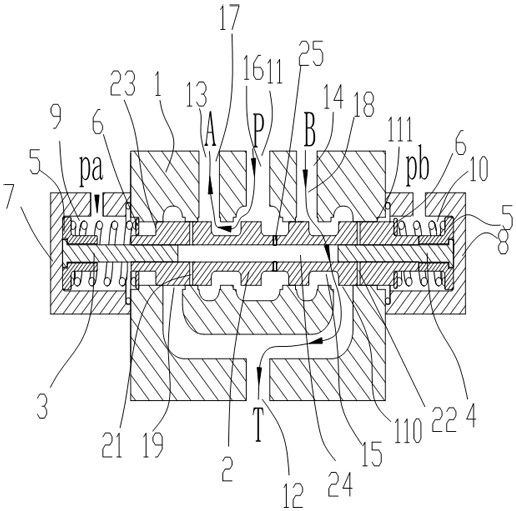
[0043] Such as Figure 1~4 , the transition function hydraulic valve in this embodiment includes a valve body 1 and a valve core 2, wherein the valve body 1 is provided with a pressure oil port 11, an oil return port and at least one working oil port, and the valve core 2 is slidably fitted on the valve body 1 Inside, the spool 2 slides to control the on-off between the pressure oil port 11, the working oil port and the oil return port.

[0044] In order to release the pressure before the connection between the pressure oil port 11 and the working oil port, the spool 2 of this embodiment is equipped with a pressure relief oil circuit. According to an embodiment of the present invention, the pressure relief oil circuit includes The oil passage 24 in the inner core and the oil inlet hole 25 and the oil discharge hole arranged on the valve core 2, the oil inlet hole 25 and the oil discharge hole are respectively connected with the oil passage 24 in the core. When the valve core 2...

Embodiment 2

[0061] Such as figure 1 As shown, the valve body 1 of this embodiment is provided with a spool hole 15, and the valve body 1 is provided with a pressure oil passage 16 communicating with the pressure oil port 11 and a working oil passage communicating with the working oil port. There are two working oil ports, and the two working oil ports are arranged on both sides of the pressure oil port 11. The oil inlet hole 25 is set corresponding to the pressure oil port 11. There are two groups of oil discharge holes, which are symmetrically arranged on the sides of the oil inlet hole 25. On both sides, there are two sets of end caps and on-off structures, which are respectively arranged at both ends of the valve body 1, and the two sets of on-off structures correspond to two sets of oil discharge holes.

[0062] Specifically, the two working oil ports are respectively the first working oil port 13 (A in the figure) and the second working oil port 14 (B in the figure), and the two end ...


PUM


Abstract

The invention relates to the technical field of hydraulic control, in particular to a hydraulic valve with transition function, comprising: a valve body, on which a pressure oil port, an oil return port and at least one working oil port are arranged; In the body, the spool slides to control the on-off between the working oil port, the pressure oil port and the oil return port; a pressure relief oil circuit is formed in the spool, and when the spool slides from the neutral position to the point where the pressure oil port communicates with the working oil port A transition position is also formed between the working positions. When the valve core is at the transition position, the pressure oil in the pressure oil port is at least partly relieved through the pressure relief oil circuit. The pressure oil port of the hydraulic valve of the present invention is partially relieved after the pressure is built up, and then the pressure oil port is connected with the working oil port, which can not only realize the high pressure of the pressure oil port at the neutral position, but also reduce the oil pressure during the rapid reversing process of the valve core. The impact of liquid on the working oil port, thereby reducing noise, improving the life of components (pipelines, valves, pumps, cylinders), and making the load move smoothly without frustration.

Description

technical field [0001] The invention relates to the technical field of hydraulic control, in particular to a transition function hydraulic valve. Background technique [0002] At present, in various walking machinery, construction machinery and some other heavy equipment, hydraulic systems and hydraulic components are widely used. Generally, the reversing valve is switched from the neutral position to the working position. For example, the patent number is 201521142639.X, and the name is A patent for wharf loading and unloading equipment, unloading arm hydraulic system and reversing valve group. After the reversing valve is reversing from the neutral position to the working position, the pressure oil after the build-up pressure directly enters the working oil port, but some valve cores need to be quickly In the working condition of reversing (the reversing time is only tens or hundreds of milliseconds), the oil pressure at the P port is directly reversed to the working oil p...

Claims


Application Information

Patent Timeline
Patent Type & Authority Patents(China)
IPC IPC(8): F15B13/02
CPCF15B13/024F15B13/02
Inventor 汪立平高雪涛杨泽贺韩日升刘红光
Owner JIANGSU HENGLI HYDRAULIC TECH CO LTD
Why Eureka
Try Eureka