
Wireless charging foreign matter detection device and method and wireless charging system

A technology for foreign object detection and wireless charging, which is applied in radio wave measurement systems, measurement devices, circuit devices, etc., to achieve the effect of improving detection blind spots.

Active Publication Date: 2021-11-05
NANJING UNIV OF AERONAUTICS & ASTRONAUTICS +1
View PDF15 Cites 1 Cited by
  • Summary
  • Abstract
  • Description
  • Claims
  • Application Information

AI Technical Summary

Problems solved by technology

In view of the above deficiencies, the present invention provides a vertical foreign object detection coil structure mainly to detect the horizontal magnetic field above the transmitting coil, which solves the problem of "detection blind spot"

Method used


Image

  • Wireless charging foreign matter detection device and method and wireless charging system
  • Wireless charging foreign matter detection device and method and wireless charging system
  • Wireless charging foreign matter detection device and method and wireless charging system

Examples


Embodiment 1

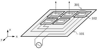
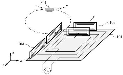
[0132] Exemplarily, Fig. 3(a) illustrates a structure of a foreign object detection coil, the transmitting coil is a horizontally wound disc coil, and the winding plane of the transmitting coil 100 is the first plane P 1 , the winding plane of the single-turn detection coil 103 is the second plane P 2 , that is, the winding plane of the coil, and the second plane is perpendicular to the first plane.

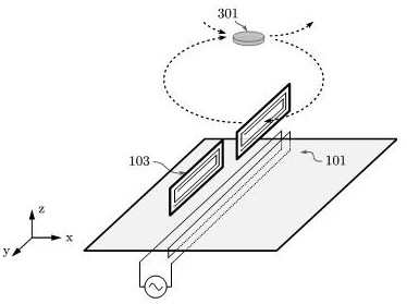
[0133] Exemplarily, Fig. 3(b) illustrates a structure of a foreign object detection coil, the transmitting coil is a solenoid coil wound vertically, and the orthogonal plane of the winding plane of the transmitting coil 100 is the first plane P 1 , the winding plane of the single-turn detection coil 103 is the second plane P 2 , that is, the winding plane of the coil, and the second plane is perpendicular to the first plane.

[0134] In fact, the detection coil will couple the eddy current magnetic field generated by the foreign object 301 above the detection coil, causing ...

Embodiment 2

[0137] Exemplarily, Fig. 4(a) illustrates a structure of a foreign object detection coil, the transmitting coil is a horizontally wound disc coil, the winding plane of the transmitting coil 100 is the first plane, and the detection coil 103 is configured to detect multi-dimensional The magnetic induction intensity; the multi-dimensional magnetic field is a magnetic field in at least two directions that do not overlap;

[0138] Exemplarily, Fig. 4(b) illustrates a structure of a foreign object detection coil, the transmitting coil is a solenoid coil wound vertically, the winding plane of the transmitting coil 100 is the first plane, and the detecting coil 103 is configured to detect multiple The magnetic induction intensity of the dimension; the multi-dimensional magnetic field is the magnetic field of at least two directions that do not overlap;

[0139] For example, when the transmitting coil 100 is a symmetrical circular coil, the magnetic field is symmetrical about the z ax...

Embodiment 3

[0146] Exemplary, Figure 5 A foreign object detection coil structure is exemplified. The difference from Embodiment 1 is that each of the six detection coils 103 is perpendicular to the first plane. In fact, the detection coil will couple the eddy current magnetic field generated by the foreign object 301 (such as the metal inside the plush toy) above the detection coil, causing one of the voltage signal of the foreign object detection coil and the current signal of the foreign object detection coil to change. Therefore, by detecting at least one of the above signals, it can be used to determine whether there is a foreign object.


PUM


Abstract

The invention provides a wireless charging foreign matter detection device and method and a wireless charging system, and belongs to the technical field of wireless charging. When a foreign matter is close to the upper part of a transmitting coil, heating is serious, but a traditional foreign matter detection scheme based on longitudinal magnetic field detection has a detection blind area above the transmitting coil. The vertical foreign matter detection coil structure is mainly used for detecting a horizontal magnetic field above a transmitting coil, and the problem of detection blind spots is solved. In addition, because the horizontal magnetic field is attenuated slowly along with the height, the structure of the invention has the capability of detecting space foreign matters at a certain height. According to the invention, foreign matter detection can be realized, safety risks caused by foreign matters can be effectively warned, and safety guarantee is provided for electric vehicles, electronic products, automatic guided transport vehicles, unmanned aerial vehicles, logistics robots, automatic driving equipment and the like with wireless charging and wireless power supply systems.

Description

technical field [0001] The present application relates to the technical field of wireless charging, and in particular to a wireless charging foreign object detection device, method and system. Background technique [0002] Wireless charging technology has been applied to electric vehicles, electronic products, automated guided vehicles (AGV, Automated Guided Vehicle), drones, logistics robots, autonomous driving and other fields, especially where automatic charging is required. Compared with contact power supply, wireless power supply has the advantages of safety, flexibility, no spark, less maintenance, mobility and easy automatic charging. A number of wireless charging related technologies and patents have been published, such as: for the non-contact transformer structure, the published patents "CN104319076B A non-contact transformer (Chen Qianhong, Hou Jia, etc.)" and "CN101630577A Edge-extended high coupling coefficient non-contact Transformers (Zhang Wei, Chen Qianhong...

Claims


Application Information

Patent Timeline
IPC IPC(8): H02J50/60H02J50/10H02J7/00G01V3/10
CPCH02J50/60H02J50/10H02J7/0047H02J7/0029G01V3/10G01V3/105
Inventor 陈乾宏张斌徐立刚温振霖任小永张之梁
Owner NANJING UNIV OF AERONAUTICS & ASTRONAUTICS
Learn More