
Bridge floor self-seepage and drainage device for road and bridge construction

A drainage device and seepage drainage technology, which is applied in the direction of heating water/sewage treatment, bridges, bridge parts, etc., can solve the problems of not being able to realize distillation and reuse, and not having the ability to dynamically adjust the flow of seepage and drainage

Inactive Publication Date: 2021-11-05
吴明辉
View PDF0 Cites 0 Cited by
  • Summary
  • Abstract
  • Description
  • Claims
  • Application Information

AI Technical Summary

Problems solved by technology

[0004] The purpose of the present invention is to provide a bridge deck self-seepage and drainage device for road and bridge construction to solve the technical problems in the prior art that do not have the ability to dynamically adjust the flow of seepage and drainage, and cannot realize distillation reuse, energy conversion and storage, etc.

Method used


Image

  • Bridge floor self-seepage and drainage device for road and bridge construction
  • Bridge floor self-seepage and drainage device for road and bridge construction
  • Bridge floor self-seepage and drainage device for road and bridge construction

Examples


Embodiment Construction

[0029] The present invention is described in detail below in conjunction with accompanying drawing:

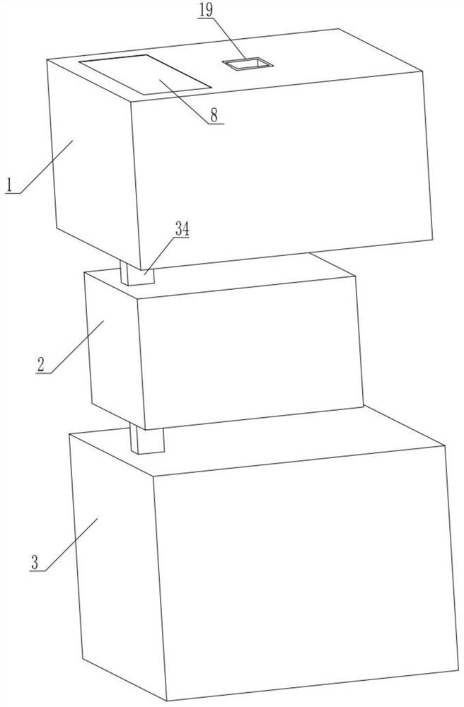
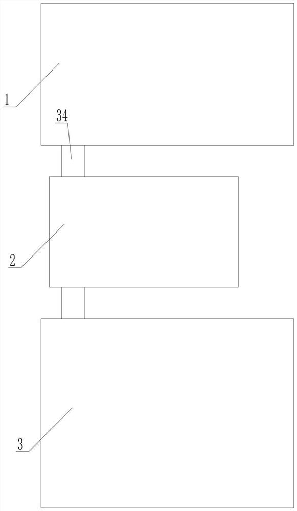
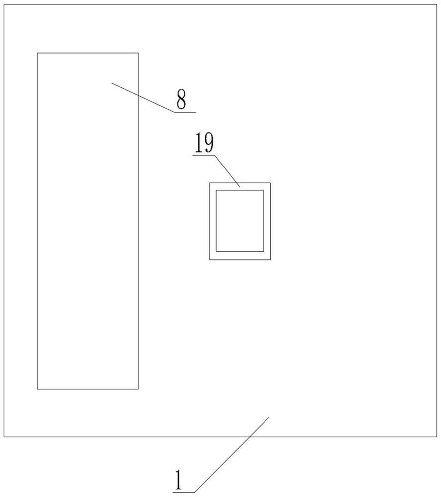
[0030] refer to Figure 1 to Figure 9 A bridge deck self-seepage and drainage device for road and bridge construction provided by the present invention includes a seepage box 1, a recovery box 2, and a power generation box 3. The top surface of the seepage box 1 is provided with a lower outlet 4, so A displacement baffle 7 is arranged directly below the lower outlet 4, the left end of the displacement baffle 7 is in contact with the right side of the left fixed inclined plate 5, and the right end of the displacement baffle 7 is in contact with the right side. The left side of the fixed sloping plate 6 contacts, the tops of the left fixed sloping plate 5 and the right fixed sloping plate 6 are fixedly connected to the inner upper side of the seepage and drainage box 1 respectively, and the lower side of the displacement baffle 7 The left part of the side is fixed with a fifth ...


PUM


Abstract

The invention provides a bridge floor self-seepage and drainage device for road and bridge construction. The device comprises a seepage and drainage box, a recycling box and a power generation box, wherein a lower drainage opening is formed in the top face of the seepage and drainage box, a displacement baffle is arranged under the lower drainage opening, the left end of the displacement baffle makes contact with the right side face of a left fixing inclined plate, the right end of the displacement baffle makes contact with the left side face of a right fixing inclined plate, the top end of the left fixing inclined plate and the top end of the right fixing inclined plate are fixedly connected with the inner upper side face of the seepage and drainage box, a fifth return spring is fixed to the left portion of the lower side face of the displacement baffle, and a spring bottom plate is fixed to the bottom end of the fifth return spring, a transmission rod is fixed to the middle of the lower side face of the displacement baffle, and a first permanent magnet is fixed to the bottom end of the transmission rod. According to the above technical scheme, the technical problems that the capacity of dynamic adjusting of seepage and drainage flow is not achieved, distillation reutilization, energy conversion and storage and the like cannot be achieved in the prior art are effectively solved, and application and popularization are facilitated.

Description

technical field [0001] The invention relates to the technical field of road and bridge construction, in particular to a bridge deck self-seepage and drainage device for road and bridge construction. Background technique [0002] With the increase of the frequency of rainstorms in various places, the drainage problem of urban roads and bridges has been highly concerned by people, and it is particularly important to improve the existing drainage system of urban roads and bridges and to develop new drainage systems. Due to the long distance between urban roads and bridges and in a relatively closed environment, water exchange with the outside world can only enter the drainage pipes through the rainwater outlets set on the roads and bridges, and finally enter the municipal pipes under the bridges. In order to quickly remove the water on the bridge and prevent the rainwater from accumulating in the road bridge and infiltrating to affect the durability of the road bridge structure...

Claims


Application Information

Patent Timeline
Patent Type & Authority Applications(China)
IPC IPC(8): E01D19/08C02F1/04
CPCE01D19/086C02F1/04C02F2103/001
Inventor 吴明辉
Owner 吴明辉
Learn More