


Quick Research
Generate reliable direction feasibility study reports for your R&D in just a few steps.

Technical Q&A
Discover and master advanced knowledge NOW. Basics, ideas, possibilities, all at once.

Find Solutions
As an expert in R&D theories, this can generate solutions to your technical problems instantly.

Evaluate Feasibility
Analyze your overall solution with one click, know your potential R&D risks in advance.

Monitor Landscape
Get weekly tech updates, stay abreast of the latest tech innovations and key insights.
Air separation system utilizing LNG cold energy and air separation method
An air separation system and cold energy technology, applied in the direction of cold treatment separation, refrigeration and liquefaction, solidification, etc., can solve the problems of high operating pressure, complex operation and maintenance, and large investment in facilities, and achieve shortened start-up time, simple operation and maintenance, and equipment low cost effect
- Summary
- Abstract
- Description
- Claims
- Application Information
AI Technical Summary
Problems solved by technology
Method used
Image

Examples
Embodiment 1
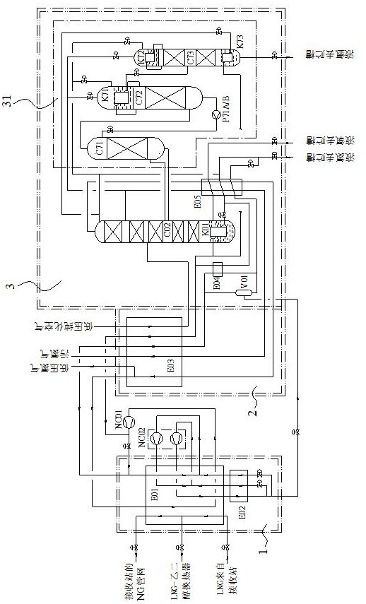
[0062] Such as figure 1 As shown, it is a structural schematic diagram of an air separation system utilizing LNG cold energy provided by the present invention, specifically a structure of an air separation system utilizing LNG cold energy to produce liquid oxygen, liquid nitrogen and liquid argon by single-column rectification schematic diagram. The air separation system includes LNG cold box unit 1, main heat exchanger cold box unit 2, main tower cold box unit 3, low-pressure nitrogen compressor NC01 and circulating nitrogen compressor NC02, etc.
[0063] Wherein, the LNG cold box unit 1 is connected with the main tower cold box unit 3 through a circulating liquid nitrogen pipeline. The cold energy generated by the vaporization of LNG in the LNG cold box unit 1 is transferred to the circulating nitrogen gas to cool and liquefy the circulating nitrogen gas to provide cold energy for the cold box unit 3 of the main tower.
[0064] The cold box unit 3 of the main tower is conn...
Embodiment 2
[0093] The present invention also provides a kind of air separation method based on the air separation system utilizing LNG cold energy described in embodiment one, the method comprises:
[0094] The LNG cold box unit 1 provides the cold energy generated by LNG vaporization for the main heat exchanger cold box unit 2 and the main tower C02 of the main tower cold box unit 3, so as to realize the cooling and liquefaction of air and nitrogen;
[0095] The cold box unit 2 of the main heat exchanger cools the low-pressure purified air and pressurized nitrogen, and sends the cooled low-pressure purified air to the main tower C02;
[0096] The main tower C02 rectifies and purifies the low-pressure purified air, obtains pure liquid oxygen at the bottom of the main tower C02, obtains pure nitrogen at the top of the tower, and obtains an argon fraction in the middle of the tower, and sends the argon fraction to the argon extraction part 31;
[0097] The argon extraction part 31 deoxygen...
PUM
 Abstract
Description
Claims
Application Information
 - R&D Engineer
- R&D Manager
- IP Professional
- Industry Leading Data Capabilities
- Powerful AI technology
- Patent DNA Extraction
Browse by: Latest US Patents, China's latest patents, Technical Efficacy Thesaurus, Application Domain, Technology Topic, Popular Technical Reports.
© 2024 PatSnap. All rights reserved.Legal|Privacy policy|Modern Slavery Act Transparency Statement|Sitemap|About US| Contact US: help@patsnap.com