
Lathe for machining ball valve body

A valve body and ball valve technology, which is applied in the field of lathes, can solve the problems of iron filings remaining and affecting workers' observation sight, and achieve the effect of blowing chips conveniently

Pending Publication Date: 2021-11-02
CHENGDU CHENGHUA MACHINERY MFG CO LTD
View PDF0 Cites 0 Cited by
  • Summary
  • Abstract
  • Description
  • Claims
  • Application Information

AI Technical Summary

Problems solved by technology

[0004] The present invention provides a lathe for processing a ball valve body to solve the problem that some iron filings generated when the valve body is bored in the above-mentioned background technology remain inside the valve body and affect the workers' observation line of sight.

Method used


Image

  • Lathe for machining ball valve body
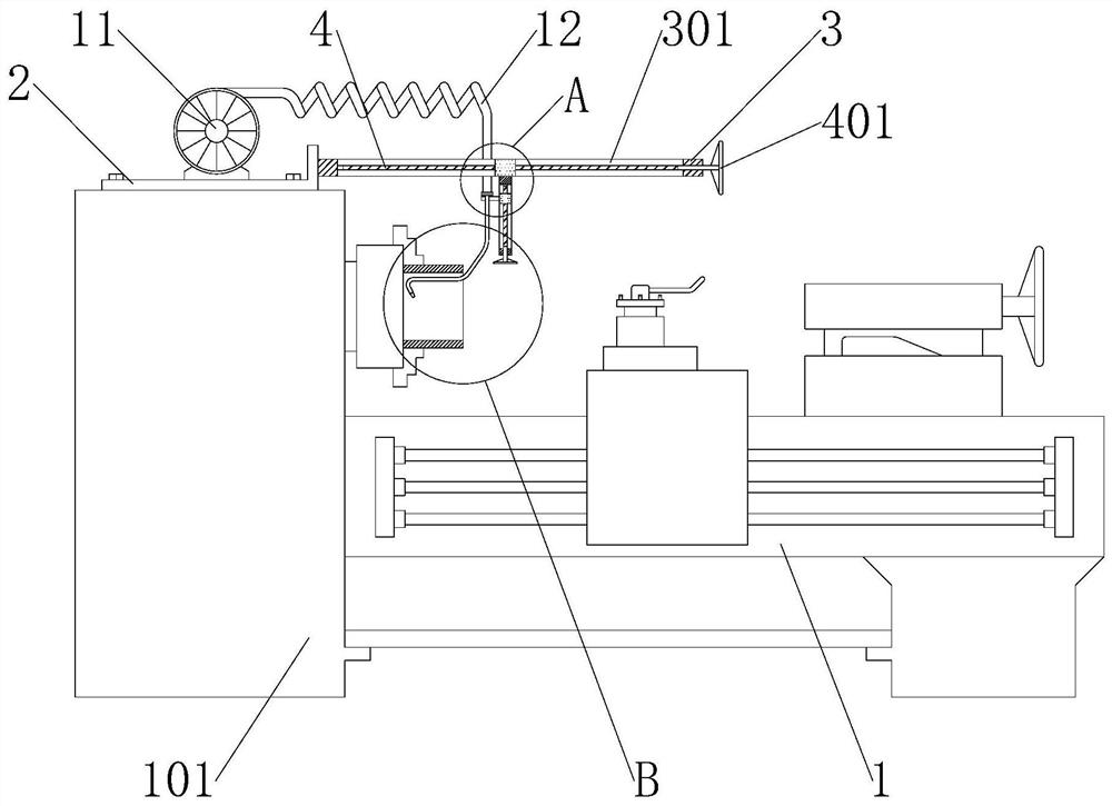
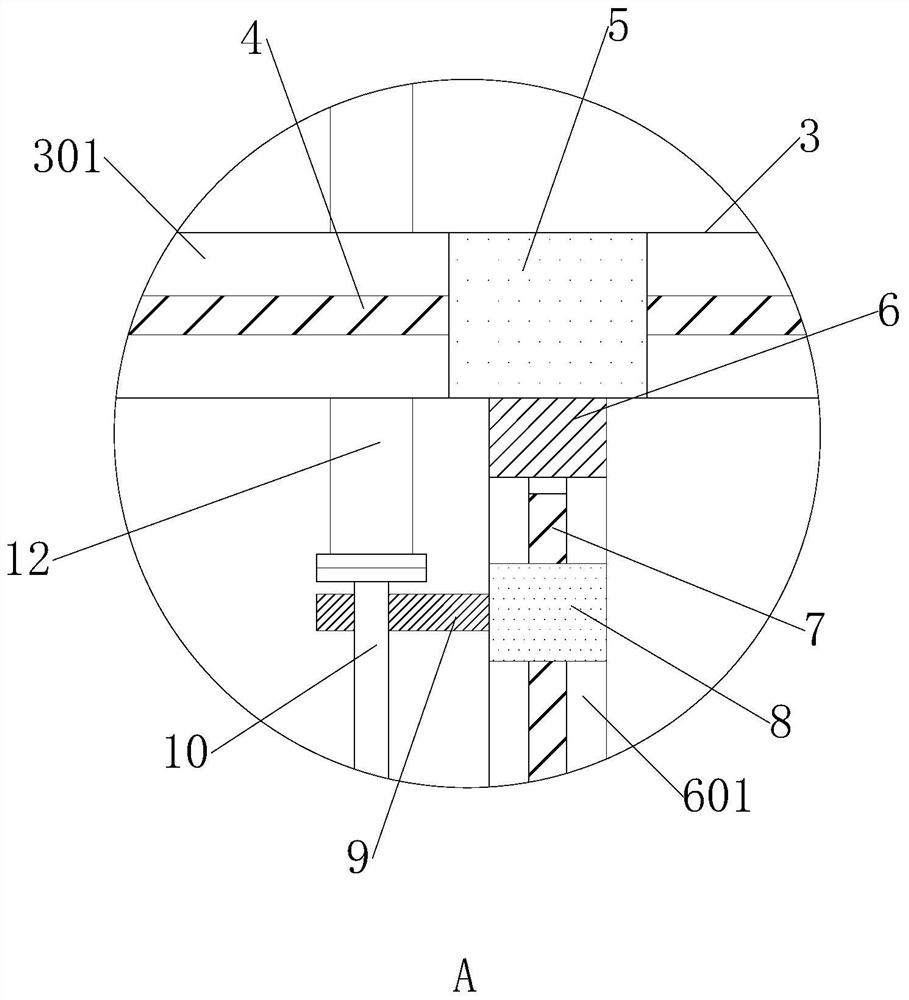
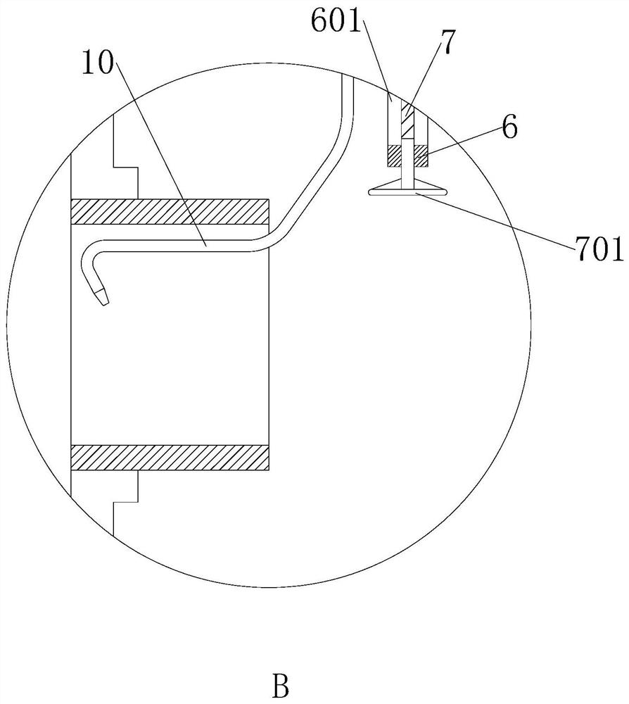
  • Lathe for machining ball valve body
  • Lathe for machining ball valve body

Examples


Embodiment Construction

[0021] see Figure 1 to Figure 3 :

[0022] The invention provides a lathe for processing a ball valve body, comprising a bed 1 and a headstock 101, the headstock 101 is installed on the left side of the bed 1, the top of the headstock 101 is installed with a mounting plate 2 through screws, and the mounting plate 2 The right side is welded with a cross bar 3, and the inside of the cross bar 3 is provided with a mobile chute 301 that is open on both sides up and down. The bottom is provided with a vertical bar 6 that can move left and right. The inside of the vertical bar 6 is provided with a lifting chute 601 that is open on both sides of the left and right sides. The inside of the lifting chute 601 is provided with a lifting slider 8 that can slide up and down. The left side of 8 is welded with a support plate 9, the bottom of the support plate 9 is plugged with a universal pipe 10, the upper surface of the mounting plate 2 is installed with a high-pressure fan 11, and the ...


PUM


Abstract

The invention discloses a lathe for machining a ball valve body, which relates to the technical field of lathes and comprises a lathe body and a spindle box; the spindle box is installed on the left side of the lathe body; an installation plate is installed at the top of the spindle box through screws; a cross rod is welded to the right side face of the installation plate; a movable sliding groove with the upper face and the lower face being open is arranged in the cross rod; a movable sliding block capable of sliding left and right is arranged in the movable sliding groove; a vertical rod capable of moving left and right is arranged under the transverse rod; a lifting sliding groove with the left face and the right face open is formed in the vertical rod; a lifting sliding block capable of sliding up and down is arranged in the lifting sliding groove; a supporting plate is welded to the left side face of the lifting sliding block; a universal pipe is inserted into the bottom of the supporting plate; and a high-pressure fan is mounted on the upper surface of the installation plate. The universal pipe is arranged above the lathe body, the bottom of the universal pipe can extend into the valve body, high-pressure air is sprayed out, scrap iron remaining in the valve body is blown away, and therefore the situation that the observation sight of workers is affected by the scrap iron is avoided.

Description

technical field [0001] The invention relates to the technical field of lathes, in particular to a lathe for processing a ball valve body. Background technique [0002] A lathe is a machine tool that mainly uses a turning tool to turn a rotating workpiece. Drills, reamers, reamers, taps, dies and knurling tools can also be used on the lathe for corresponding processing. [0003] When using an ordinary lathe to bore the ball valve body, part of the iron filings generated by the boring will remain inside the valve body, and the accumulated iron filings will affect the worker's observation line of sight, which will affect the machining accuracy of the valve body , for this reason we have proposed a kind of lathe for ball valve valve body processing, to solve the technical problems raised above. Contents of the invention [0004] The present invention provides a lathe for processing a ball valve body to solve the problem that part of the iron filings generated when the valve ...

Claims


Application Information

Patent Timeline
Patent Type & Authority Applications(China)
IPC IPC(8): B23B41/00B23B47/00B23Q11/00
CPCB23B41/00B23B47/00B23Q11/005
Inventor 欧国胜赖大福李心召
Owner CHENGDU CHENGHUA MACHINERY MFG CO LTD
Learn More