Industrial sewage microfiltration device
A technology for industrial sewage and filtration devices, which is applied in filtration separation, filtration loops, mobile filter element filters, etc. Microfiltration efficiency and performance, prolonging service life, and promoting the effect of slag discharge
- Summary
- Abstract
- Description
- Claims
- Application Information
AI Technical Summary
Problems solved by technology
Method used
Image
Examples
Embodiment example 1
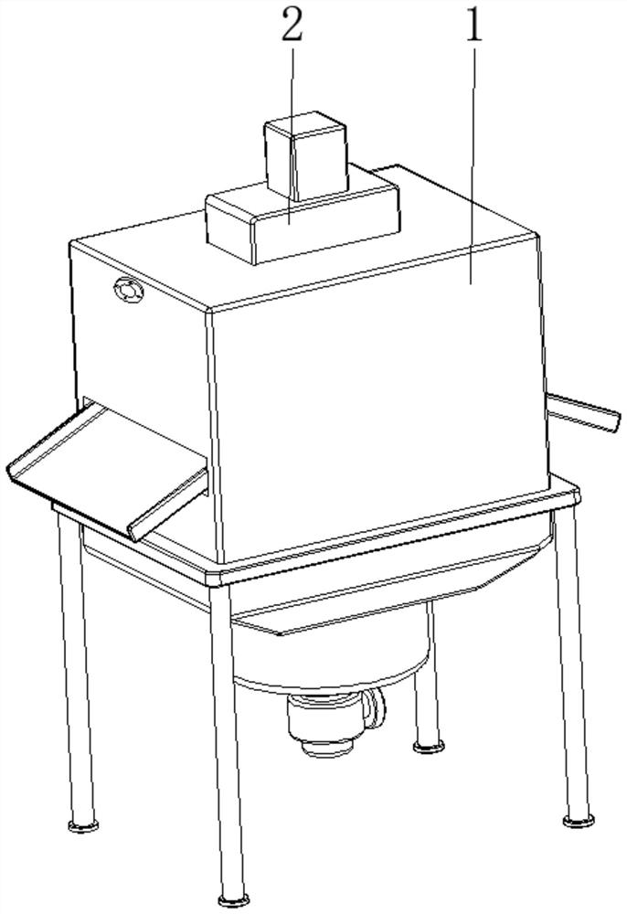
[0029] see Figure 1-6 , the present invention provides a technical solution: a microfiltration device for industrial sewage, comprising a sewage filtration chamber 1, a power mechanism 2, and the power mechanism 2 is arranged at the top central position of the sewage filtration chamber 1;
[0030] The inside of the sewage filter chamber 1 is provided with a crushing device 3, a sewage input pipe 4, a filter device 5, a connecting spring 6, and a conical micro-filter 7. The input pipe 4 is arranged on the surface top side of the crushing device 3 and is positioned at the inside of the sewage filter chamber 1, and the end of the sewage input pipe 4 away from the crushing device 3 penetrates the inwall of the sewage filter chamber 1 and extends to the outside, and the filter device 5 is arranged on The inside of the sewage filter chamber 1 is located at the surface position, the connecting spring 6 is arranged at the bottom of the filter device 5 and near the top position, the c...
Embodiment example 2
[0032] The crushing device 3 is provided with a cylindrical barrel 31, fixed teeth 32, a rotating shaft 33, a rotating tooth 34, and a pressure head device 35. On the inner wall, the rotating shaft 33 is arranged at the inner central position of the cylinder 31 and is rotationally connected with the top of the sewage filter chamber 1, the top of the rotating shaft 33 is connected with the power mechanism 2, and the rotating tooth 34 is fixed on the surface of the rotating shaft 33 and located Inside the cylinder 31 , the pressure head device 35 is fixed on the bottom end of the rotating shaft 33 .
[0033] The pressure head device 35 is provided with a pressure head base block 351 and an inclined surface 352. The top of the pressure head base block 351 is fixedly connected with the bottom end of the rotating shaft 33. The inclined surface 352 is set on the bottom of the pressure head base block 351. When the sewage is input When the pipe 4 transports the industrial sewage into...
Embodiment example 3
[0035]The filter device 5 is provided with an inclined bucket 51, a filter plate 52, an arc spring 53, and an inertia impact device 54. The inclined bucket 51 is rotatably connected to the inner wall of the sewage filter chamber 1, the filter plate 52 is arranged on the surface of the inclined bucket 51, and the arc spring 53 is fixed between the bottom of the inclined bucket 51 and the two sides corresponding to the inner wall of the sewage filter chamber 1, and the inertial impact device 54 is arranged on the bottom of the filter plate 52, and with the continuous rotation of the pressure head base block 351, combined with the inclined surface 352 The impact of the filter plate 52 is pressed, combined with the elastic force of the arc spring 53, and then the tilting bucket 51 is reciprocated to promote slag discharge. At the same time, the swing of the tilting bucket 51 is combined with the principle of inertia. Impact on the filter plate 52 to realize the effect of self-clean...
PUM
 Abstract
Description
Claims
Application Information
 - Generate Ideas
- Intellectual Property
- Life Sciences
- Materials
- Tech Scout
- Unparalleled Data Quality
- Higher Quality Content
- 60% Fewer Hallucinations
Browse by: Latest US Patents, China's latest patents, Technical Efficacy Thesaurus, Application Domain, Technology Topic, Popular Technical Reports.
© 2025 PatSnap. All rights reserved.Legal|Privacy policy|Modern Slavery Act Transparency Statement|Sitemap|About US| Contact US: help@patsnap.com


