
Fuel tank arrangement in marine vessel and method of relieving hydrogen from liquid hydrogen fuel tank arrangement

A fuel tank and liquid hydrogen technology, which is applied in the liquid hydrogen fuel tank device to release hydrogen to avoid fire or explosion.

Active Publication Date: 2021-10-29
WARTSILA FINLAND OY
View PDF12 Cites 0 Cited by
  • Summary
  • Abstract
  • Description
  • Claims
  • Application Information

AI Technical Summary

Problems solved by technology

[0007] Another issue in liquid hydrogen systems is the temperature of the hydrogen gas that must be removed to the outside atmosphere

Method used


Image

  • Fuel tank arrangement in marine vessel and method of relieving hydrogen from liquid hydrogen fuel tank arrangement
  • Fuel tank arrangement in marine vessel and method of relieving hydrogen from liquid hydrogen fuel tank arrangement
  • Fuel tank arrangement in marine vessel and method of relieving hydrogen from liquid hydrogen fuel tank arrangement

Examples


Embodiment Construction

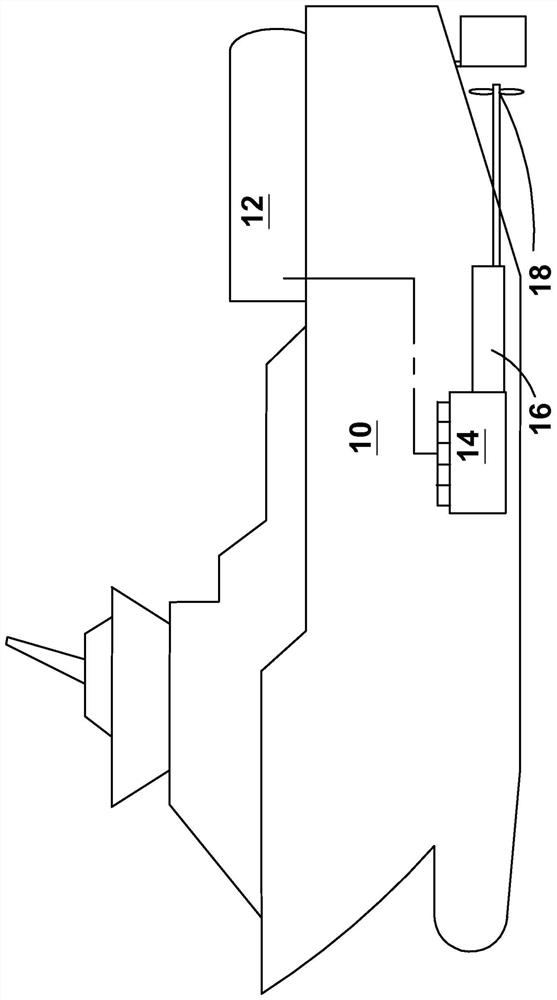
[0029] figure 1 In a very simplified manner and schematically shown is a marine vessel 10 having a liquid hydrogen fuel tank arrangement 12 according to a first preferred embodiment of the invention arranged on its deck. Naturally, liquid hydrogen fuel tanks could also be located below deck. The figure also shows an internal combustion engine 14 (a fuel cell or any other energy conversion device using hydrogen that receives fuel from a liquid hydrogen fuel tank device 12, more broadly a power unit), and the coupling to the fuel cell / internal combustion engine / power unit Drive 16 for both propeller and propeller 18. However, it should be noted that the propulsion system may of course be of any known type. The drive here can comprise a mechanical gear or a generator-electric drive combination.

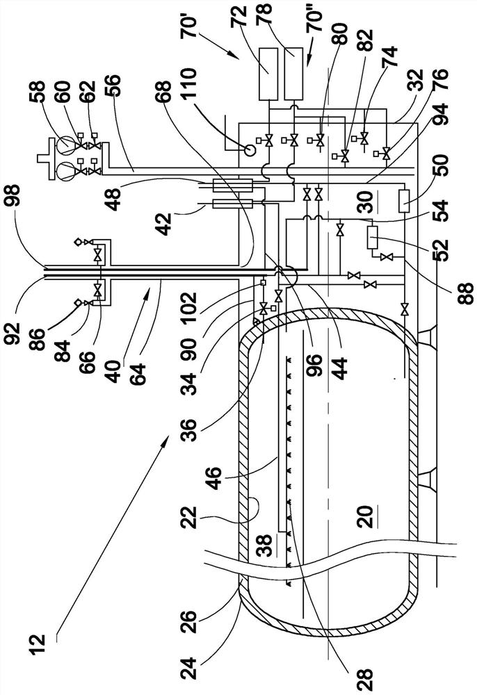
[0030] figure 2 A longitudinal cross-section of the liquid hydrogen fuel tank arrangement 12 is illustrated in more detail but still in a schematic and simplified manner. The fuel ...


PUM


Abstract

The present invention relates to a fuel tank arrangement of a marine vessel, the tank arrangement (12) comprising a liquid hydrogen fuel tank (20), a tank connection space (30) arranged in communication with the liquid hydrogen fuel tank (20), the tank connection space (30) being provided with a vent mast (40) having a lower end and an upper end, and an interior, the interior of the vent mast (40) forming a ventilation outlet line (62) for discharging gas from the tank connection space (30), an emergency pressure relief valve (34) coupled via a safety valve line (36) to the gas space (38) of the fuel tank (20), wherein a first hydrogen outlet line (92) provided in the vent mast (40) is separate from the ventilation outlet line (64), the first hydrogen outlet line (92) extending from the lower end of the vent mast (40) to the upper end thereof and being arranged in flow communication with the emergency pressure relief valve (34).

Description

technical field [0001] The present invention relates to a fuel tank arrangement for storing liquid hydrogen in a sea vessel and a method for releasing hydrogen from the liquid hydrogen fuel tank arrangement. More specifically, the present invention relates to such a liquid hydrogen fuel tank device: the tank includes at least two casings, a heat insulator between the at least two casings, and a liquid hydrogen fuel tank arranged at one end or a Side box connection space. Background technique [0002] In recent years, the LH 2 (Liquid Hydrogen) for use as a fuel for sea, land and air applications, where LH 2 Used in internal combustion engines, fuel cells or rocket engines. [0003] A fuel tank arrangement for liquid hydrogen includes the same basic elements as a tank arrangement for liquefied natural gas (LNG), ie, the fuel tank itself and a tank connection space. The tank connection space is usually an airtight enclosure constructed of cryogenic material and contains al...

Claims


Application Information

Patent Timeline
IPC IPC(8): F17C3/04F17C3/08F17C9/02F17C13/12
CPCF17C2225/044F17C9/02F17C2221/012F17C2205/0352F17C2227/0393F17C2205/0358F17C2225/033F17C2227/0107F17C2205/0367F17C2201/035F17C2203/0629F17C2250/0439F17C13/123F17C2205/0332F17C2227/044F17C2203/032F17C2227/0309F17C2250/032F17C2250/043F17C3/04F17C2223/043F17C2225/046F17C2223/0161F17C2225/0123F17C2205/0326F17C2201/0109F17C3/08F17C2203/0341F17C2223/033F17C2201/054F17C2203/0391F17C2223/046F17C2250/0452F17C2250/0636F17C2250/0626F17C2250/0631F17C2250/0647F17C2260/015F17C2260/042F17C2260/037F17C2265/066F17C2270/0105Y02E60/32B63H21/17B63H2021/003B63J2/06B63J2/10H01M2250/20H01M8/04201H01M8/04365H01M8/043B63B25/16
Inventor L·维斯特博斯塔德T·诺顿
Owner WARTSILA FINLAND OY
Learn More