Magnetic light angle measurement system and method based on quantum weak measurement
A measurement method and measurement system technology, which is applied in the measurement of magnetic variables, measurement devices, and the size/direction of the magnetic field, can solve the problem of limiting the measurement accuracy of the magneto-optical effect, and the inability to separate the magneto-optic rotation angle and magneto-optic ellipticity at the same time. Accurate measurement and other issues, to achieve the effect of good application prospects, high sensitivity, wide application prospects
- Summary
- Abstract
- Description
- Claims
- Application Information
AI Technical Summary
Problems solved by technology
Method used
Image
Examples
Embodiment 1
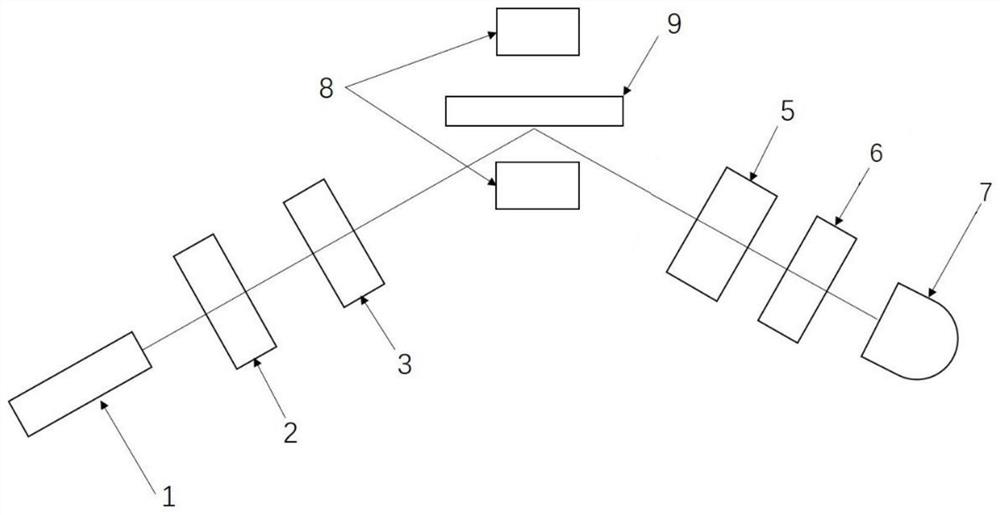
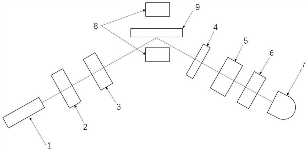
[0048] The complex magneto-optical angle measuring device based on quantum weak measurement provided in this embodiment is suitable for measuring the complex magneto-optical angle in the magneto-optical Kerr effect (reflection method), such as figure 1 and figure 2 As shown, it includes a light-emitting device, a polarization state preparer 3 , an electromagnetic field generating device 8 , a phase adjusting device 4 , a time delay device 5 , a polarization state detector 6 and a photodetector 7 .
[0049] The light-emitting device is used to provide a light beam, and includes a light source generator 1 and a light intensity attenuator 2 arranged in sequence. The light source generator 1 is mainly used to provide a polarized light source. In this embodiment, the light source generator 1 can emit a collimated light beam with a center wavelength of 633 nm and a spectral width of 10 nm. The light intensity attenuator 2 is used to attenuate the light power emitted by the light s...
Embodiment 2
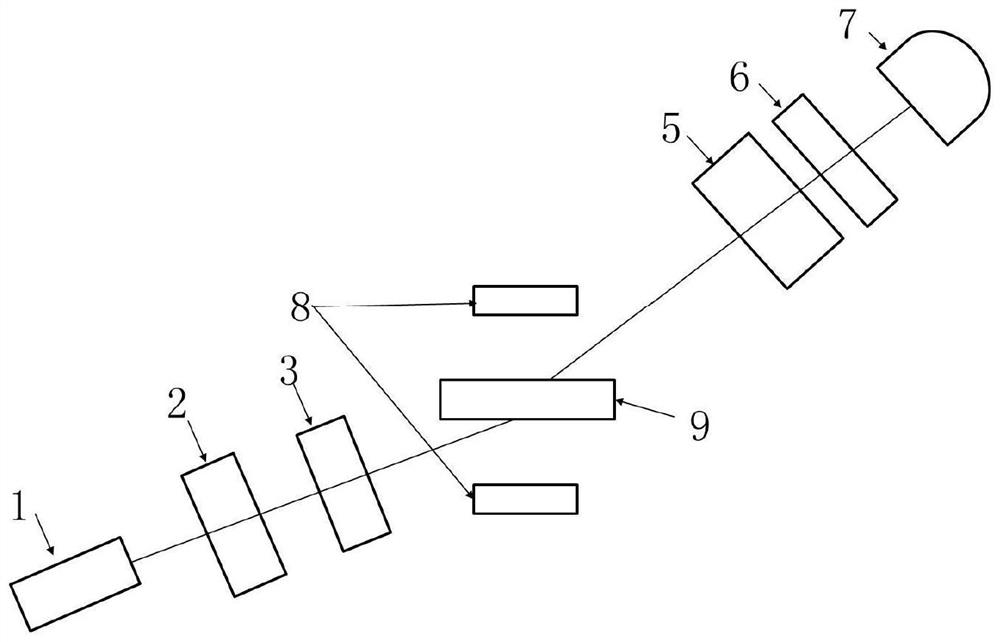
[0058] The complex magneto-optical angle measuring device based on quantum weak measurement provided in this embodiment is suitable for measuring the complex magneto-optical angle in the magneto-optical Faraday effect (transmission method), such as image 3 and Figure 4 As shown, it includes a light-emitting device, a polarization state preparer 3 , an electromagnetic field generating device 8 , a phase adjusting device 4 , a time delay device 5 , a polarization state detector 6 and a photodetector 7 .
[0059] The light-emitting device is used to provide a light beam, and includes a light source generator 1 and a light intensity attenuator 2 arranged in sequence. The light source generator 1 is mainly used to provide a polarized light source. In this embodiment, the light source generator 1 can emit a collimated light beam with a center wavelength of 633 nm and a spectral width of 10 nm. The light intensity attenuator 2 is used to attenuate the light power emitted by the li...
Embodiment 3
[0067] The complex magneto-optical angle measurement method based on quantum weak measurement provided in this embodiment is measured based on the measurement device provided in Embodiment 1, and specifically includes the following steps:
[0068] Step 1. Initial setting
[0069] The sample 9 to be tested is placed in the working cavity of the electromagnetic field generating device according to the set direction, and under the condition of zero magnetic field, the light-emitting device is activated, and the light-emitting device emits a collimated beam with a center wavelength of 633 nm and a spectral width of 10 nm. The plane-polarized light transformed into the horizontal polarization state |H> by the polarization state preparer 3 is incident on the surface of the sample 9 to be tested, and the plane-polarized light reflected by the surface of the sample is converted into elliptically polarized light, and after the reflected light passes through the time delay device 5, The...
PUM
| Property | Measurement | Unit |
|---|---|---|
| wavelength | aaaaa | aaaaa |
| magnetic field | aaaaa | aaaaa |
| Sensitivity | aaaaa | aaaaa |
Abstract
Description
Claims
Application Information
 - R&D
- Intellectual Property
- Life Sciences
- Materials
- Tech Scout
- Unparalleled Data Quality
- Higher Quality Content
- 60% Fewer Hallucinations
Browse by: Latest US Patents, China's latest patents, Technical Efficacy Thesaurus, Application Domain, Technology Topic, Popular Technical Reports.
© 2025 PatSnap. All rights reserved.Legal|Privacy policy|Modern Slavery Act Transparency Statement|Sitemap|About US| Contact US: help@patsnap.com


