
Optical fingerprint acquisition device for preventing interference of covering

A technology of fingerprint collection and covering, which is applied in the direction of cleaning methods using tools, cleaning methods using liquids, chemical instruments and methods, etc., which can solve the problems of fingerprint collection interference, interference collection effect, inconvenient use, etc., to ensure cleanliness , Improve the effect of cleaning efficiency

Pending Publication Date: 2021-10-22
深圳市光千合新材料科技有限公司
View PDF0 Cites 0 Cited by
  • Summary
  • Abstract
  • Description
  • Claims
  • Application Information

AI Technical Summary

Problems solved by technology

[0003] When the existing punching equipment for optical fingerprint collection is in use, the lighting glass is usually exposed to the outside air, and the dust in the air will fall on the surface of the glass, so that the dust will interfere with the collection effect during fingerprint collection, and the human body The skin of the human body will secrete oil. When collecting fingerprints, you will press your finger on the outside of the glass, so that a layer of oil will adhere to the surface of the glass, which will interfere with subsequent fingerprint collection. The existing method is to attach a layer of oil to the outside of the glass However, the protective film needs to be replaced after the protective film is used for a long time. Usually, the protective film needs to be torn off and replaced, which is very inconvenient to use.

Method used


Image

  • Optical fingerprint acquisition device for preventing interference of covering
  • Optical fingerprint acquisition device for preventing interference of covering
  • Optical fingerprint acquisition device for preventing interference of covering

Examples


Embodiment Construction

[0036] The following will clearly and completely describe the technical solutions in the embodiments of the present invention with reference to the drawings in the embodiments of the present invention. The embodiments described below by referring to the figures are exemplary only for explaining the present invention and should not be construed as limiting the present invention.

[0037] The embodiments of the present invention will be described below according to the overall structure of the present invention.

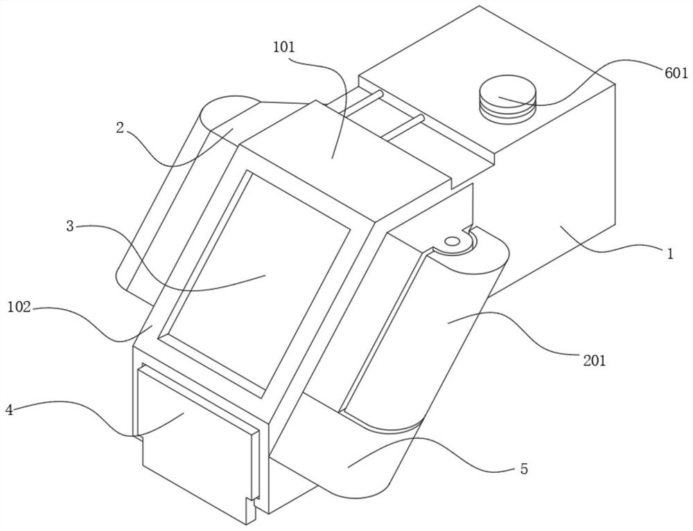
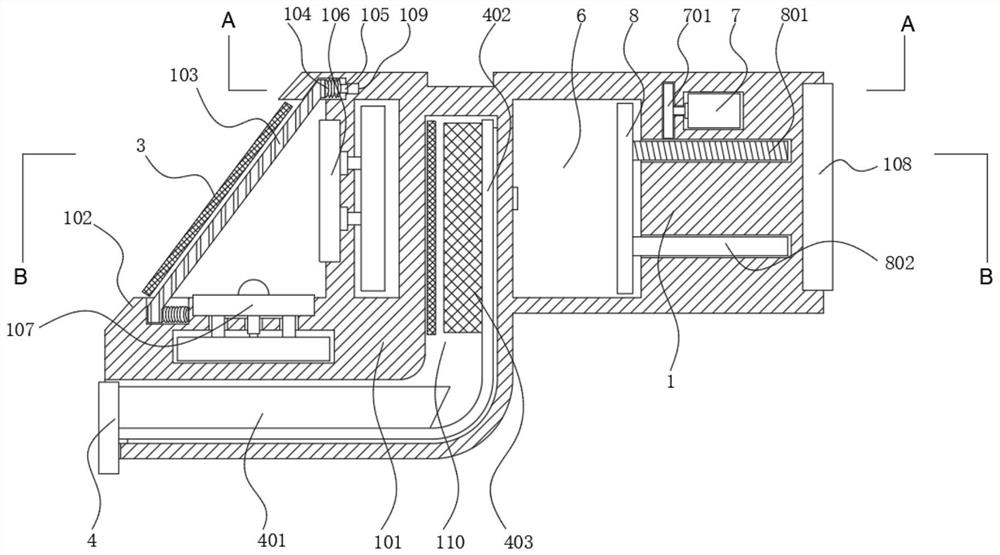
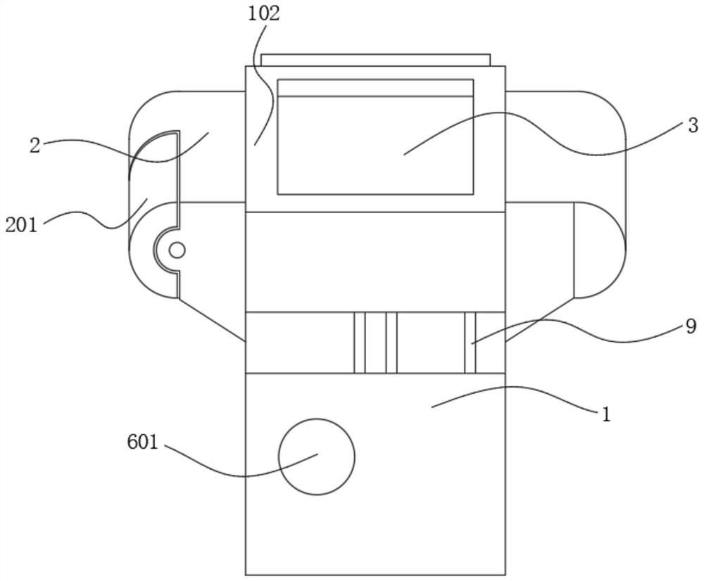
[0038] An optical fingerprint collection device for preventing interference from coverings, such as Figure 1 to Figure 8As shown, the main body shell 1 is included, and the inclined plane shell 101 is installed on one side of the main body shell 1, and the end surface of the inclined plane shell 101 is provided with a frame 102, and the inside of the frame 102 is equipped with a glass 103, and the bottom end of the inclined plane shell 101 is installed with a Light-e...


PUM


Abstract

The invention discloses an optical fingerprint acquisition device for preventing interference of covering, and relates to the field of optical fingerprint acquisition, the optical fingerprint acquisition device comprises a main body shell, one side of the main body shell is provided with an inclined plane shell, the end face of the inclined plane shell is provided with a frame, the frame is internally provided with glass, and the bottom end of the interior of the inclined plane shell is provided with a light emitting diode; a charge coupler is installed on the inner wall of the inclined face shell, a single chip microcomputer is installed on the end face of the main body shell, a clamping groove is formed between the main body shell and the inclined face shell, the clamping groove is in an L shape, and outer edge shells are obliquely arranged on the two sides of the inclined face shell. According to the device, through arrangement of a pulling plate, bristles can be pushed to move to the outer side of a protective film, cleaning liquid obtained after cleaning can be collected, waste cleaning liquid is prevented from flowing randomly, unnecessary damage to the device is avoided, operation of a pushing motor is controlled through extrusion of fingers on glass, and the cleaning efficiency is improved.

Description

technical field [0001] The invention relates to the field of optical fingerprint collection, in particular to an optical fingerprint collection device for preventing interference from coverings. Background technique [0002] Optical fingerprint collection technology is the oldest and most widely used fingerprint collection technology at present. Optical fingerprint collection equipment began in 1971. Its principle is the total reflection of light. The light shines on the glass surface with fingerprints, and the reflected light is obtained by CCD. , the light is totally reflected at the interface between the glass and the air after being irradiated by the glass to the valley, and the light is reflected to the CCD, while the light directed to the ridge does not undergo total reflection, but is absorbed or diffusely reflected by the contact surface between the ridge and the glass In other places, a clear fingerprint image is formed on the CCD, and now optical fingerprint collec...

Claims


Application Information

Patent Timeline
IPC IPC(8): G06K9/00B08B3/02B08B1/02B08B13/00
CPCB08B3/02B08B13/00B08B1/12B08B1/20
Inventor 刘瑶蔡蔚然刘泳琳
Owner 深圳市光千合新材料科技有限公司
Learn More