
Water cooling equipment for clean production of copper alloy

A clean production, copper alloy technology, applied in household refrigeration devices, lighting and heating equipment, applications, etc., can solve the problems of reducing water cooling efficiency, easy heating of rollers, affecting the effect of copper alloy water cooling, etc., to prevent the wheel body from overheating. , the effect of improving efficiency

Pending Publication Date: 2021-10-22
郑浩源
View PDF7 Cites 0 Cited by
  • Summary
  • Abstract
  • Description
  • Claims
  • Application Information

AI Technical Summary

Problems solved by technology

[0003] When the existing copper alloy is water-cooled, the two sides are generally moved by means of roller transmission, but because the roller rotates for a long time and rubs against the copper alloy plate, the roller is prone to heat, which affects the water cooling on both sides of the copper alloy. effect, reducing water cooling efficiency

Method used


Image

  • Water cooling equipment for clean production of copper alloy
  • Water cooling equipment for clean production of copper alloy
  • Water cooling equipment for clean production of copper alloy

Examples


Embodiment 1

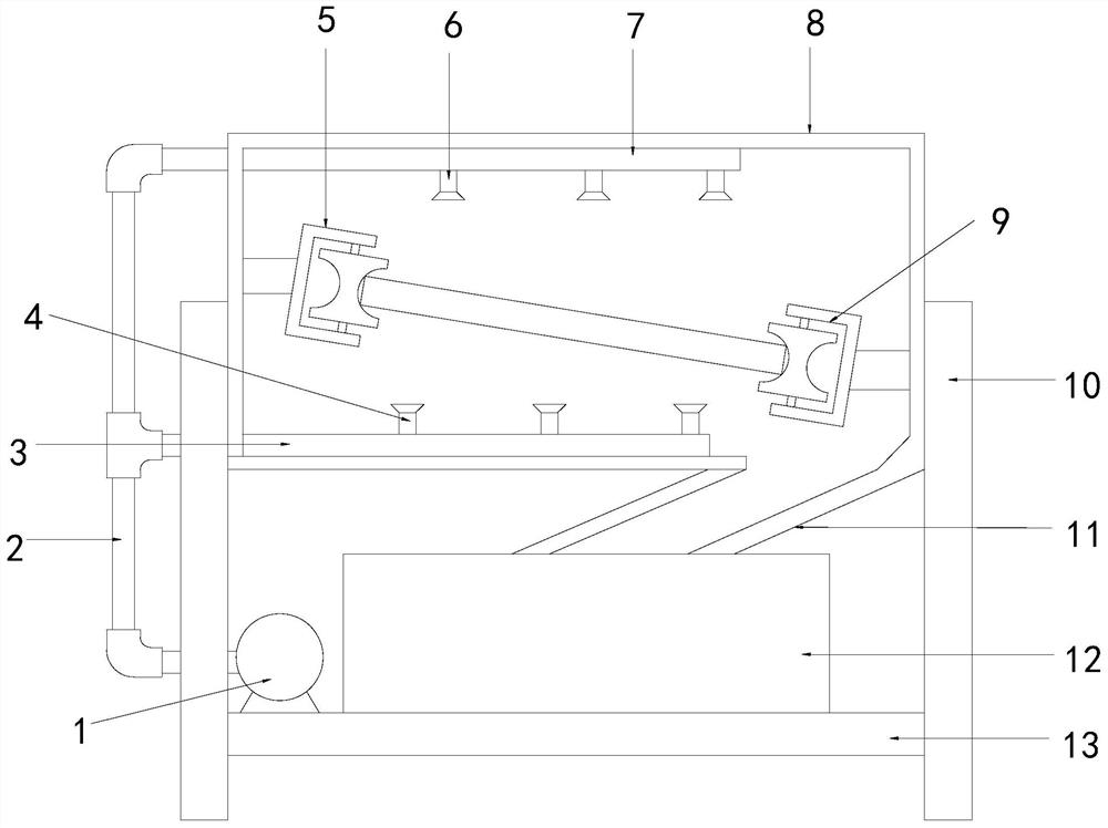
[0027] see figure 1 , the present invention provides a technical solution for copper alloy clean production water cooling equipment: its structure includes a water pump 1, a main water pipe 2, a lower water pipe 3, a lower nozzle 4, a left roller 5, an upper nozzle 6, an upper water pipe 7, a water cooling box 8, Right roller 9, support 10, outlet pipe 11, water storage tank 12, support plate 13, the left and right sides of described water cooling box 8 are connected with support 10 top, and described support 10 bottom is welded with support plate 13, and described support plate 13 is provided with a water storage tank 12 and a water pump 1. The bottom of the water cooling tank 8 is connected to the water storage tank 12 through the outlet pipe 11. The left roller 5 and the right roller 9 are respectively arranged on both sides of the inside of the water cooling tank 8. The upper and lower sides of the box 8 are respectively provided with an upper water pipe 7 and a lower wat...

Embodiment 2

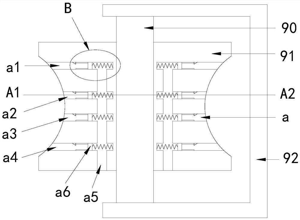
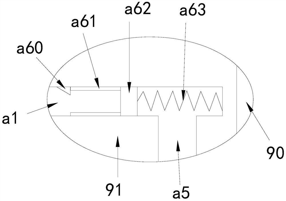
[0030] see Figure 1-4 , the present invention provides a technical solution for copper alloy clean production water cooling equipment: its structure includes a water pump 1, a main water pipe 2, a lower water pipe 3, a lower nozzle 4, a left roller 5, an upper nozzle 6, an upper water pipe 7, a water cooling box 8, Right roller 9, support 10, outlet pipe 11, water storage tank 12, support plate 13, the left and right sides of described water cooling box 8 are connected with support 10 top, and described support 10 bottom is welded with support plate 13, and described support plate 13 is provided with a water storage tank 12 and a water pump 1. The bottom of the water cooling tank 8 is connected to the water storage tank 12 through the outlet pipe 11. The left roller 5 and the right roller 9 are respectively arranged on both sides of the inside of the water cooling tank 8. The upper and lower sides of the box 8 are respectively provided with an upper water pipe 7 and a lower w...


PUM


Abstract

The invention discloses water cooling equipment for clean production of a copper alloy. The water cooling equipment structurally comprises a water pump, a main water pipe, a lower water pipe, lower spray heads, a left roller, upper spray heads, an upper water pipe, a water cooling tank, a right roller, a support, a water outlet pipe, a water storage tank and a supporting plate, the left side and the right side of the water cooling tank are connected with the top of the support, the supporting plate is welded to the bottom of the support, the water storage tank and the water pump are arranged on the supporting plate, the bottom of the water cooling tank is in communication with the water storage tank through the water outlet pipe, a left roller and a right roller are arranged on the two sides in the water cooling tank correspondingly, the upper water pipe and the lower water pipe are arranged on the upper face and the lower face of the water cooling tank correspondingly, and the uniformly distributed upper spray heads are arranged at the bottom of the upper water pipe. Cold water or cold air can actively and quickly pass through a channel through magnetic force so as to be cooled, and can be continuously cooled along with rotation of a wheel body, so that the temperature of the wheel body is prevented from being overheated, the left roller and the right roller can be continuously cooled, and the cooling effect of a copper alloy plate is prevented from being influenced.

Description

technical field [0001] The invention relates to the technical field of water cooling equipment, in particular to water cooling equipment for clean production of copper alloys. Background technique [0002] Copper alloy is the most widely used non-ferrous metal structural material in industry. With the rapid development of industrial economy, the demand for copper alloy products is increasing. At present, water is needed to cool cast aluminum workpieces in the production process of copper alloy. [0003] When the existing copper alloy is water-cooled, the two sides are generally moved by means of roller transmission, but because the roller rotates for a long time and rubs against the copper alloy plate, the roller is prone to heat, which affects the water cooling on both sides of the copper alloy. effect, reducing water cooling efficiency. Contents of the invention [0004] The main purpose of the present invention is to overcome the deficiencies of the prior art and provi...

Claims


Application Information

Patent Timeline
Patent Type & Authority Applications(China)
IPC IPC(8): F25D17/02B22D30/00
CPCF25D17/02B22D30/00
Inventor 郑浩源
Owner 郑浩源
Learn More