
A degreasing agent separation oil pollution regeneration device

A technology of regeneration device and degreasing agent, which is applied in the direction of grease/oily substance/suspton removal device, separation method, liquid separation, etc., which can solve the problem of fluctuations in the degreasing liquid level of the regeneration device, inaccurate control of heating and demulsification temperature, and inability to discharge Oil pollution and other problems to achieve the effect of reducing energy consumption

Active Publication Date: 2022-05-03
DONGFENG COMML VEHICLE CO LTD
View PDF6 Cites 0 Cited by
  • Summary
  • Abstract
  • Description
  • Claims
  • Application Information

AI Technical Summary

Problems solved by technology

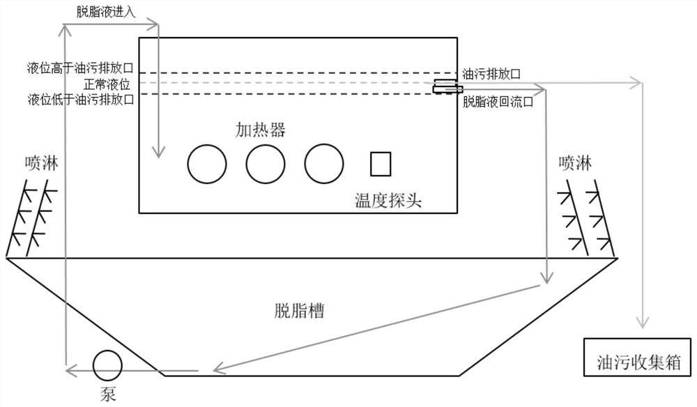
[0004] Disadvantages of the existing heating method to remove oil in the degreasing agent: because the flow rate of the degreasing agent containing oil into the regeneration device is not constant (influenced by pipeline blockage and other reasons), the degreasing liquid level of the regeneration device fluctuates
The heating demulsification temperature control is inaccurate. When the temperature is too high, the surfactant in the degreasing agent will be precipitated, resulting in the failure of the regenerated degreasing agent.
[0005] Disadvantages of the existing ultrafiltration method for removing oil in degreasing agents: there are tiny metal oxides and dust on the surface of steel plates in the automotive coating industry, which will block the pores in the microporous materials. will be invalid
[0006] Disadvantages of the existing adsorption method to remove oil stains in degreasing agents: in the automotive coating industry, the output is high, and the surface of steel plates is more oily.
High replacement cost for oil-wet and impure materials
[0007] For example, the patent CN101653666 provides a kind of heating and demulsification oil-water separation equipment, which is equipped with an oil-water separation device structure 5, which has the following defects: 1. Due to the influence of pipeline blockage and other reasons, the liquid level fluctuates, and the flow rate of the degreasing liquid is small. The surface is lower than the discharge port, and the oil cannot be discharged; when the flow rate of the degreasing agent is large, the liquid level is higher than the oil discharge port, and the degreasing liquid and the oil are discharged into the subsequent stage, which will waste the degreasing agent, so the pump 14 is used to recover the degreasing liquid; 2. It is necessary to frequently adjust the manual valve 1 to control the flow rate; 3. There is no heat exchanger structure; 4. The degreasing liquid is returned to the degreasing tank through the pump 15, which requires the use of multiple pumps, the degreasing tank circulation pump, pump 14 , 15 pumps, 3 in total; 5. The oil and degreasing liquid are separated using an overflow port (structure 5), which cannot completely separate the oil and the degreasing liquid. To remove oil stains, it is necessary to manually open the waste oil discharge pipe through the observation window; 6. Several The tank body is separated but not separated, and a horizontal plane is integrated, but there is a partition in the middle

Method used


Image

  • A degreasing agent separation oil pollution regeneration device
  • A degreasing agent separation oil pollution regeneration device
  • A degreasing agent separation oil pollution regeneration device

Examples


Embodiment Construction

[0041] The technical solutions of the present invention will be clearly and completely described below in conjunction with the accompanying drawings. Apparently, the described embodiments are some of the embodiments of the present invention, but not all of them. Based on the embodiments of the present invention, all other embodiments obtained by persons of ordinary skill in the art without making creative efforts belong to the protection scope of the present invention.

[0042] In the description of the present invention, it should be noted that unless otherwise specified and limited, the terms "installation", "connection" and "connection" should be understood in a broad sense, for example, it can be a fixed connection or a detachable connection. Connected, or integrally connected; it may be mechanically connected or electrically connected; it may be directly connected or indirectly connected through an intermediary, and it may be the internal communication of two components. ...


PUM


Abstract

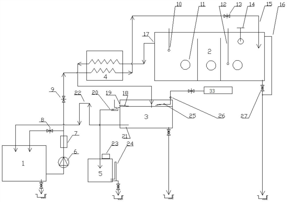
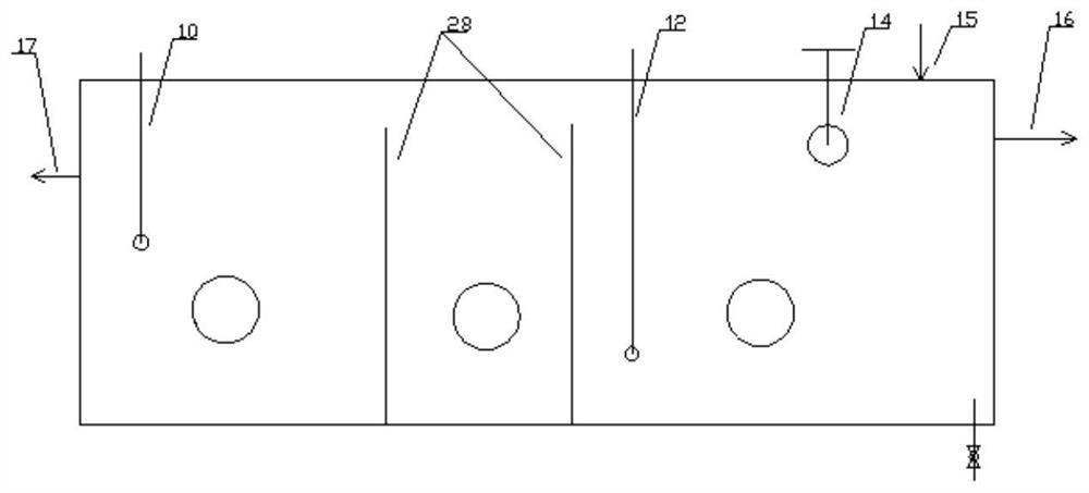
The invention discloses a degreasing agent separation oil pollution regeneration device. It includes a degreasing tank, and also includes a heating tank arranged at different heights, a heat exchanger, an oil skimming tank, and an oil dirt collection box, the heating tank is arranged higher than the heat exchanger, and the heat exchanger is arranged higher than the oil skimming tank, The skimming tank is arranged higher than the degreasing tank, and the degreasing tank is arranged higher than the oil dirt collection tank; the pipeline between the degreasing tank and the heat exchanger is provided with a degreasing tank circulating pump, a degreasing filter and a switch for switching The first degreasing and degreasing pipeline control valve, an unbroken degreasing agent inlet pipeline and a heated demulsifying degreasing agent outflow pipeline are arranged between the heat exchanger and the heating tank, and the undemulsifying degreasing agent inlet pipeline is provided with There is a second degreasing and oil-removing pipeline control valve for adjusting the flow rate, a curved pipeline is provided between the degreasing tank and the oil-skimming dirt tank, and the heat exchanger is connected to the oil-skimming dirt tank through a pipeline. The invention does not separately install a pump body, uses the degreasing tank circulation pump to drive the unbroken degreasing agent into the heating tank, and uses the gravity of the degreasing agent to realize the return of the clean degreasing agent to the degreasing tank, and the oily dirt flows to the collection box.

Description

technical field [0001] The invention belongs to the technical field of pretreatment in the automobile painting industry, and in particular relates to a degreasing agent separation oil pollution regeneration device. Background technique [0002] Before the car cab is painted, oil stains are attached to the surface of the steel plate, which needs to be removed with a pre-treatment degreasing agent. With the continuous use of the degreasing agent, the oil on the surface of the steel plate in the cab continues to enter the degreasing agent, causing the oil content in the degreasing agent to increase continuously, and the ability of the degreasing agent to remove oil stains decreases. Therefore, it is necessary to regularly scrap the whole tank of degreasing agent. In view of the above problems, a set of degreasing agent separation and oil pollution regeneration device is designed to separate the oil in the degreasing agent through demulsification, so that the degreasing agent c...

Claims


Application Information

Patent Timeline
Patent Type & Authority Patents(China)
IPC IPC(8): C02F1/40
CPCC02F1/40
Inventor 胡耀宇姜云中王伟耿远胜姜海龙杨齐志
Owner DONGFENG COMML VEHICLE CO LTD
Learn More