
Rotor position angle determination method and device based on permanent magnet synchronous motor

A technology of permanent magnet synchronous motor and rotor position angle, which is applied in the direction of control of electromechanical transmission, control of generator, motor control, etc., and can solve the problems of reduced accuracy, general lack of adaptability, and inapplicability to various situations

Pending Publication Date: 2021-10-19
POWERVISION TECH
View PDF6 Cites 1 Cited by
  • Summary
  • Abstract
  • Description
  • Claims
  • Application Information

AI Technical Summary

Problems solved by technology

However, it has been found in practice that FOC control requires precise rotor position angles to participate in the calculation, and all current methods for determining rotor position angles will reduce their accuracy due to changes or fluctuations in the rotational speed, making them unsuitable for many situations. This leads to the obvious deficiency of its general adaptability

Method used


Image

  • Rotor position angle determination method and device based on permanent magnet synchronous motor
  • Rotor position angle determination method and device based on permanent magnet synchronous motor
  • Rotor position angle determination method and device based on permanent magnet synchronous motor

Examples


Embodiment 1

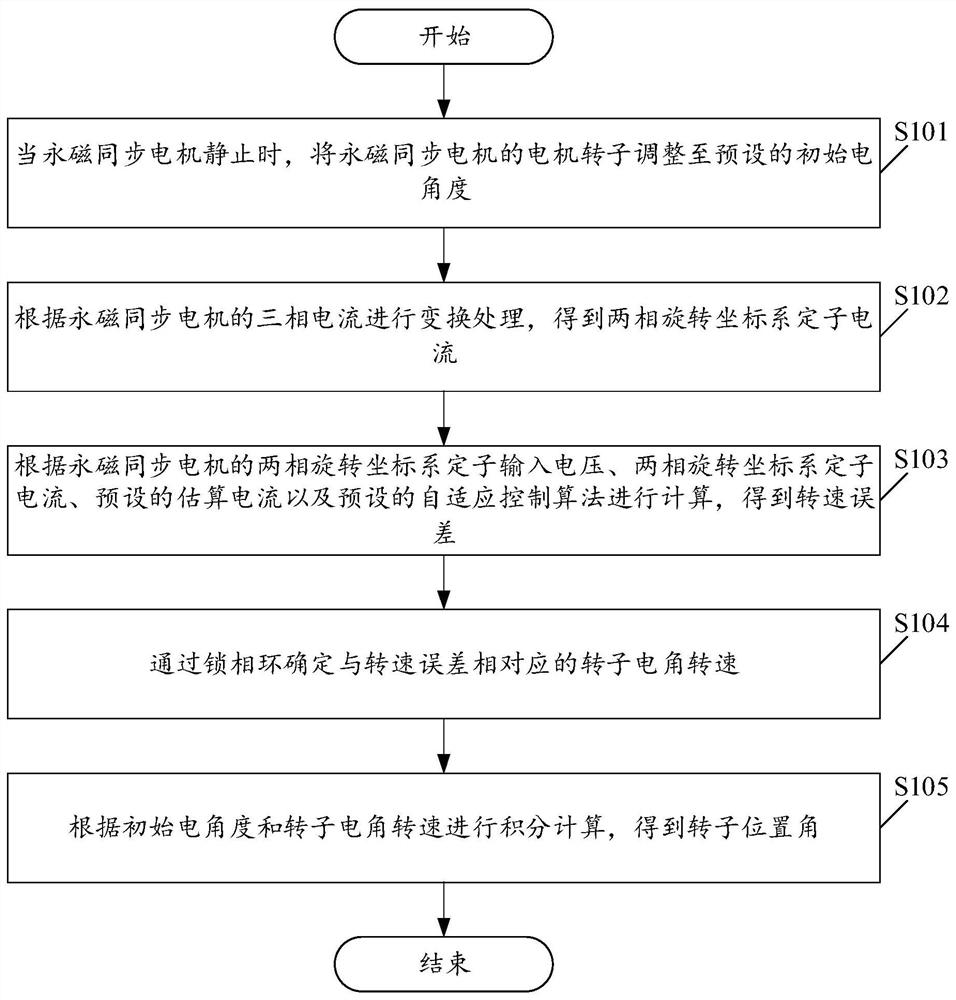
[0055] Please see figure 1 , figure 1 A schematic flowchart of a method for determining a rotor position angle based on a permanent magnet synchronous motor is provided for an embodiment of the present application. Wherein, the method for determining the rotor position angle based on the permanent magnet synchronous motor includes:

[0056] S101. When the permanent magnet synchronous motor is stationary, adjust the motor rotor of the permanent magnet synchronous motor to a preset initial electrical angle.

[0057] In this embodiment, when the permanent magnet synchronous motor is stationary, the method can control the upper bridge arm of the three-phase inverter A phase to open and the lower bridge arm to close, and the upper bridge arms of the B and C phases to close and the lower bridge arm to open. The DC torque at this time will drag the motor rotor to the position of zero electrical angle, so as to realize the precise positioning of the rotor.

[0058] S102. Perform tr...

Embodiment 2

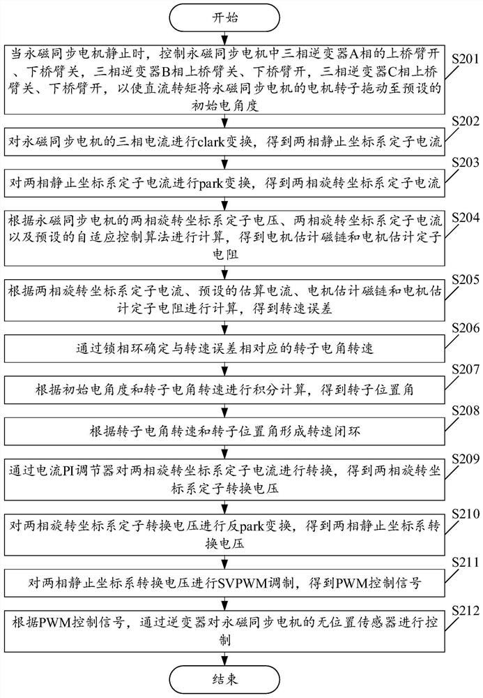
[0072] Please see figure 2 , figure 2 It is a schematic flowchart of a method for determining a rotor position angle based on a permanent magnet synchronous motor provided in an embodiment of the present application. like figure 2 As shown, wherein, the method for determining the rotor position angle based on the permanent magnet synchronous motor includes:

[0073] S201. When the permanent magnet synchronous motor is at rest, control the upper bridge arm of the three-phase inverter A phase to open and the lower bridge arm to close, and the three-phase inverter B phase upper bridge arm to close and the lower bridge arm to open , the upper bridge arm of phase C of the three-phase inverter is closed, and the lower bridge arm is opened, so that the DC torque will drag the motor rotor of the permanent magnet synchronous motor to a preset initial electrical angle.

[0074] S202 , performing clark transformation on the three-phase current of the permanent magnet synchronous mo...

Embodiment 3

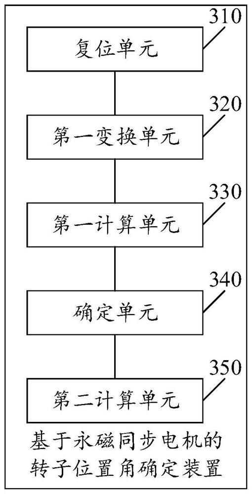
[0110] Please see image 3 , image 3 A schematic structural diagram of a device for determining a rotor position angle based on a permanent magnet synchronous motor provided in an embodiment of the present application. like image 3 As shown, the rotor position angle determination device based on permanent magnet synchronous motor includes:

[0111] The reset unit 310 is used to adjust the motor rotor of the permanent magnet synchronous motor to a preset initial electrical angle when the permanent magnet synchronous motor is stationary;

[0112] The first conversion unit 320 is configured to perform conversion processing according to the three-phase current of the permanent magnet synchronous motor to obtain the stator current of the two-phase rotating coordinate system;

[0113] The first calculation unit 330 is used to perform calculations based on the stator input voltage of the two-phase rotating coordinate system of the permanent magnet synchronous motor, the stator c...


PUM


Abstract

The embodiment of the invention provides a rotor position angle determination method and device based on a permanent magnet synchronous motor. The method comprises the steps of adjusting a motor rotor of the permanent magnet synchronous motor to a preset initial electrical angle when the permanent magnet synchronous motor is static, performing conversion processing according to the three-phase current of the permanent magnet synchronous motor to obtain a two-phase rotating coordinate system stator current, calculating according to the two-phase rotating coordinate system stator input voltage and the two-phase rotating coordinate system stator current of the permanent magnet synchronous motor, a preset estimated current and a preset self-adaptive control algorithm to obtain a rotating speed error, determining a rotor electrical angle rotating speed corresponding to the rotating speed error through a phase-locked loop, and performing integral calculation according to the initial electrical angle and the rotor electrical angle rotating speed to obtain a rotor position angle. Therefore, by implementing the implementation mode, the method can be suitable for various rotating speed conditions, so that the general adaptive capacity is improved, and the performance reliability and stability of the permanent magnet synchronous motor are further improved.

Description

technical field [0001] The present application relates to the technical field of motor drive, in particular, to a method and device for determining a rotor position angle based on a permanent magnet synchronous motor. Background technique [0002] FOC (Field-Oriented Control), that is, field-oriented control, also known as vector frequency conversion, is currently the best choice for efficient control of brushless DC motors (BLDC) and permanent magnet synchronous motors (PMSM). FOC precisely controls the magnitude and direction of the magnetic field, making the motor torque stable, low noise, high efficiency, and high-speed dynamic response. However, it has been found in practice that FOC control requires precise rotor position angles to participate in the calculation, and all current methods for determining rotor position angles will reduce their accuracy due to changes or fluctuations in the rotational speed, making them unsuitable for many situations. And then led to the...

Claims


Application Information

Patent Timeline
Patent Type & Authority Applications(China)
IPC IPC(8): H02P21/18H02P21/24H02P25/026H02P27/08
CPCH02P21/18H02P21/24H02P25/026H02P27/08H02P2207/05
Inventor 不公告发明人
Owner POWERVISION TECH
Learn More