Real-time indicating circuit for overcurrent fault of single capacitor in large number of capacitors connected in parallel

A technology for indicating circuit and overcurrent faults, applied in the direction of measuring current/voltage, measuring electricity, measuring electrical variables, etc., can solve the problems of shortened service life, inconvenient maintenance to protect normal capacitance, and large damage, etc., to achieve convenient and timely processing , Easy to repair and maintain in time, the effect of simple circuit

Inactive Publication Date: 2021-10-19
SOUTHWESTERN INST OF PHYSICS
View PDF9 Cites 0 Cited by
  • Summary
  • Abstract
  • Description
  • Claims
  • Application Information

AI Technical Summary

Problems solved by technology

[0006] The technical problem to be solved by the present invention is that when a large number of capacitors are connected in parallel, there is a narrow pulse current with a large peak value output by the capacitor, which will cause great damage to it and shorten the service life; In which position, it is not convenient to repair and maintain in time to protect the normal capacitor
The purpose of the present invention is to provide a single capacitor overcurrent fault real-time indication circuit when a large number of capacitors are connected in parallel, so as to solve the above technical problems existing in the parallel connection of a large number of capacitors

Method used


Image

  • Real-time indicating circuit for overcurrent fault of single capacitor in large number of capacitors connected in parallel
  • Real-time indicating circuit for overcurrent fault of single capacitor in large number of capacitors connected in parallel

Examples


Embodiment

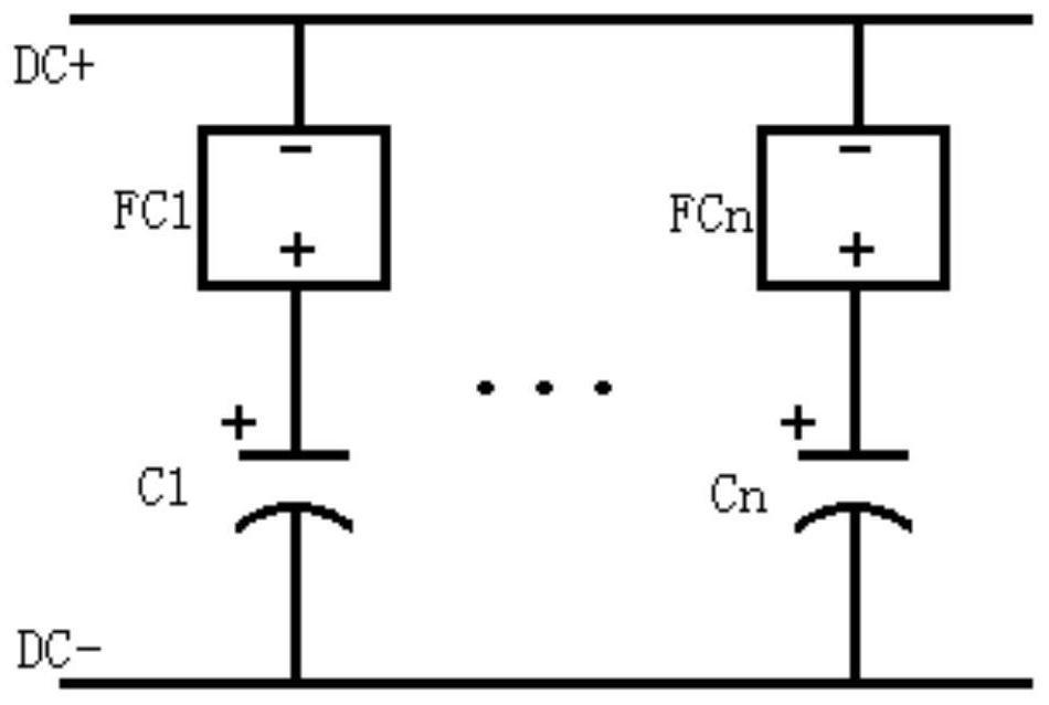
[0030] Such as figure 1 , figure 2 As shown, a real-time indication circuit for a single capacitor overcurrent fault when a large number of capacitors are connected in parallel includes several capacitors (C1, ..., Cn), each of which is connected in parallel, and one capacitor is connected in series with a corresponding capacitor overcurrent fault Real-time indication circuit, capacitor C1 is connected to capacitor overcurrent fault real-time indication circuit FC1, ..., capacitor Cn is connected to capacitor over-current fault real-time indication circuit FCn;

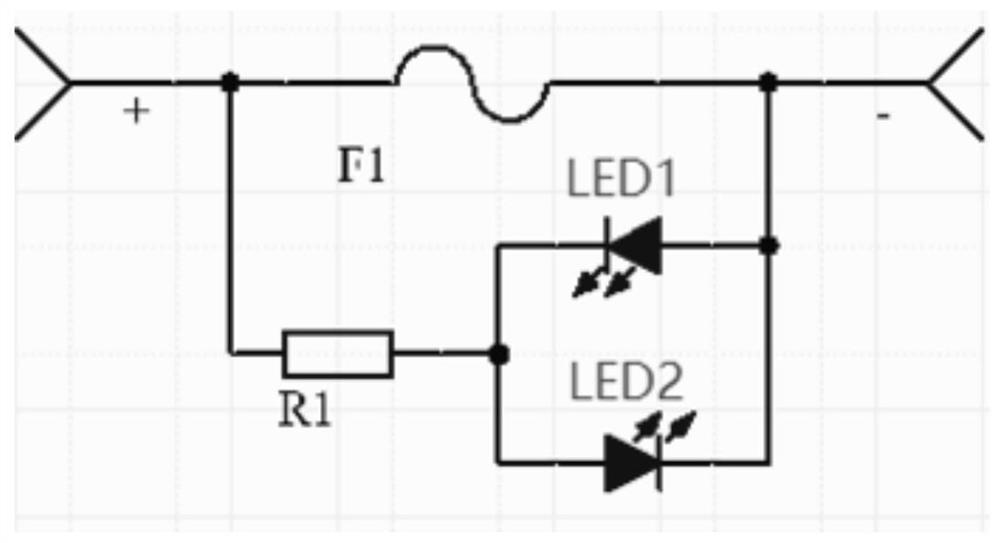
[0031] The positive pole of each capacitor is connected to the first end of the corresponding capacitor overcurrent fault real-time indication circuit (i.e. the capacitor overcurrent fault real-time indication circuit circuit board), each of the capacitor overcurrent fault real-time indication circuit (i.e. the capacitor overcurrent fault real-time The second end of the indicating circuit circuit board) is connected...

Embodiment 2

[0044] Such as figure 1 , figure 2 As shown, the difference between this embodiment and Embodiment 1 is that a single capacitor overcurrent fault real-time indication circuit in Embodiment 1 is installed in the magnetic field coil power supply of the spherical tokamak device when a large number of capacitors are connected in parallel, and the spherical tokamak The magnetic field coil power supply of the device includes at least one thousand capacitors connected in parallel, and each capacitor is provided with the capacitor overcurrent fault real-time indication circuit, and the capacitor overcurrent fault real-time indication circuit indicates whether the corresponding capacitor is faulty or charged and discharged. flow.

[0045] At first, it can be defined that the red light of the light-emitting diode indicates that the capacitor fuse is disconnected, and its voltage is greater than the normal working capacitor voltage; the blue light is on, indicating that the capacitor f...


PUM


Abstract

The invention discloses a real-time indicating circuit for an overcurrent fault of a single capacitor in a large number of capacitors connected in parallel. The circuit comprises a plurality of capacitors which are connected in parallel, and each capacitor is connected in series with a corresponding capacitor overcurrent fault real-time indicating circuit; the positive electrode of each capacitor is connected with the first end of the corresponding capacitor overcurrent fault real-time indicating circuit, and the second end of each capacitor overcurrent fault real-time indicating circuit is connected with the positive electrode of a direct-current power supply; the negative electrode of each capacitor is connected with the negative electrode of the direct-current power supply; each capacitor overcurrent fault real-time indicating circuit comprises a fuse F, a resistor R and a parallel indication circuit, and the parallel indication circuit comprises a forward indication lamp and a reverse indication lamp. The circuit is simple and reasonable, is suitable for occasions with fuses, and is used for indicating whether the fuses are fused or not; based on a large number of capacitors connected in parallel, the circuit is easy to find the position of the capacitor with the overcurrent fault in a large number of capacitors connected in parallel, and is convenient to repair and maintain in time to protect normal capacitors.

Description

technical field [0001] The invention relates to the technical field of capacitor overcurrent fault detection, in particular to a single capacitor overcurrent fault real-time indication circuit when a large number of capacitors are connected in parallel. Background technique [0002] Existing capacitor overcurrent fault detection schemes judge capacitor faults by comparing real-time capacitor voltage waveforms with reference waveforms. The application scenario is the impact on circuit waveforms after capacitor faults; there is no fault detection scheme for capacitor discharge or charging overcurrent . [0003] Capacitors are used as energy storage elements. When a large number of capacitors are connected in parallel, there are two problems: [0004] (1) The capacitor outputs a narrow pulse current with a large peak value, which will greatly damage it and shorten its service life; [0005] (2) There are a large number of capacitors connected in parallel, and it is not known ...

Claims


Application Information

Patent Timeline
Patent Type & Authority Applications(China)
IPC IPC(8): G01R31/00G01R19/165
CPCG01R31/00G01R19/16571
Inventor 陈俊宏戟洋王英翘宣伟民姚列英李维斌郑雪韩艾玻邓茂才甘辉张建金庆华钱锋
Owner SOUTHWESTERN INST OF PHYSICS
Why Eureka
Try Eureka