Supercharge Your Innovation With Domain-Expert AI Agents!

Conductive heating type drying bin

A conduction heating and drying chamber technology, applied in the field of drying chambers, can solve the problems of increased power consumption of the drying chamber, difficulty in repairing, scrapped and unusable drying chambers, etc., and achieves the effect of improving the service life

Inactive Publication Date: 2021-10-19
MENGZHOU YUANHONG DRYING EQUIP RES & DEV CO LTD
View PDF4 Cites 0 Cited by
  • Summary
  • Abstract
  • Description
  • Claims
  • Application Information

AI Technical Summary

Problems solved by technology

Under the sloshing stress of the metal pipe, the weld between the heat dissipation pipe (equivalent to the metal pipe in this application) and the warehouse body is easily damaged and leaks. The leak point is not easy to check and repair. It caused the scrapping of the dry warehouse and made it unusable
[0005] In order to have high resistance and high torsion resistance performance between the drying chamber body and the metal pipe, the only way to increase the thickness of the metal plate of the drying chamber body is to increase the connection area between the chamber body and the heat dissipation pipe, so that the drying of the thick metal plate chamber body The production cost of the warehouse increases; the weight of the drying warehouse increases, and the power consumption required for the operation of the drying warehouse also increases

Method used


Image

  • Conductive heating type drying bin
  • Conductive heating type drying bin
  • Conductive heating type drying bin

Examples


Embodiment 1

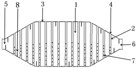
[0044] like figure 1 , figure 2 The drum-type conduction heating drying chamber shown includes a drying chamber 1 , a metal pipe 2 and a spiral blade 8 .

[0045] The drying bin 1 is a drum drying bin.

[0046]The bin body 3 of the drying bin 1 is made of metal plate, and the thickness of the bin body 3 is 2mm; the metal plate is processed into a drum drying bin through cutting, rolling, welding, polishing, inspection and the like.

[0047] The drying bin 1 has a feed port 5 and a discharge port 6 .

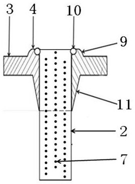
[0048] The chamber body 3 of the drying chamber 1 has a hot-melt hole 4, and the hot-melt hole 4 and the warehouse body 3 are integrated; The part protruding below the warehouse body 3 is the taper sleeve 11 . The aperture of the hot-melt hole 4 is the same as the diameter of the metal pipe 2; the distance between the hot-melt hole 4 and the hot-melt hole 4 is 60mm.

[0049] The hole length of the hot melt hole 4 is 8mm, and the hole diameter of the hot melt hole 4 is 25.4m...

Embodiment 2

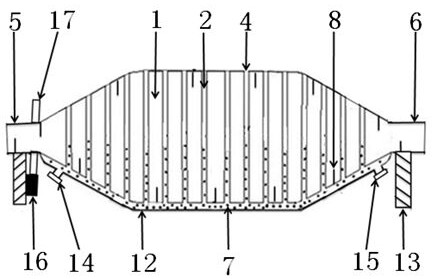
[0061] like Figure 4 , figure 2 The shown double-cone conductive heating drying chamber includes a drying chamber 1 , a metal pipe 2 and an exhaust pipe 18 .

[0062] like Figure 4 , figure 2 The structure of the double-cone conduction heating drying chamber shown in Embodiment 2 and the drum conduction heating drying chamber introduced in Embodiment 1 will not be repeated.

[0063] The drying bin 1 is a double-cone drying bin.

[0064] There is a feeding port 5 on the drying bin 1 .

[0065] The two ends of the metal pipe 2 are inserted into the upper and lower corresponding hot-melt holes 4 of the chamber body 3 of the drying bin 1, and the outside of the metal pipe 2 is tightly attached to the hole surface in the hot-melt hole 4, and the pipe of the metal pipe 2 The boss 9 of the head and the heat fusion hole 4 is fixedly welded as one, and it is airtight between the pipe head of the welded metal pipe 2 and the boss 9 of the heat fusion hole 4.

[0066] One end of...


PUM

PropertyMeasurementUnit
Thicknessaaaaaaaaaa
Apertureaaaaaaaaaa
Thicknessaaaaaaaaaa

Abstract

The invention provides a conductive heating type drying bin which comprises a drying bin body and a metal pipe. The drying bin is a double-cone drying bin or a single-cone drying bin or a roller drying bin. Two ends of the metal pipe are inserted into the upper and lower corresponding hot melting holes of the drying bin body, and the a head of the metal pipe and the bosses of the hot melting holes are fixedly welded into a whole. The bosses of the hot melting holes have certain widths and thicknesses, and the bin body of the thin metal plate with the hot melting holes has low requirements on the welding process. Under the supporting effect of a hot melting hole taper sleeve thick wall layer, the metal pipe has high resistance and high torsion resistance, the welding position between the metal pipe and the bosses of the hot melting holes cannot be damaged under the shaking stress effect of the metal pipe, and the service life of the conductive heating type drying bin is prolonged.

Description

[0001] The invention relates to a drying bin used in conjunction with drying equipment, in particular to a conduction heating type drying bin. Background technique [0002] Chinese Patent Literature Publication No. CN105222577B Stereo Heating Type Vacuum Drying Chamber, CN105318680B Stereo Heating Type Double Cone Vacuum Dryer. tube); the two ends of the heat dissipation pipe are inserted into the corresponding openings of the inner shell (equivalent to the drying warehouse body of this application); the bonding position of the heat dissipation pipe and the inner shell is welded as a whole. [0003] Chinese Patent Literature Publication No. CN105423739B is a heat pipe drying bin that can utilize waste heat, and CN105444551B is a rotating drying bin with a cooling section, and the two ends of the heat dissipation standpipe (equivalent to the metal pipe of the present application) are inserted into the corresponding openings on the drying bin body. ; Use a welding machine to wel...

Claims


Application Information

Patent Timeline
IPC IPC(8): F26B11/06F26B23/10F26B25/00
CPCF26B11/0477F26B23/10F26B25/00
Inventor 程长青
Owner MENGZHOU YUANHONG DRYING EQUIP RES & DEV CO LTD
Features
  • R&D
  • Intellectual Property
  • Life Sciences
  • Materials
  • Tech Scout
  • Unparalleled Data Quality
  • Higher Quality Content
  • 60% Fewer Hallucinations
Learn More