
Five-axis redundant fiber-optic gyroscope measuring device structure

A fiber optic gyroscope and measuring device technology, applied in the field of inertial measurement, can solve the problems of single point failure, no redundant design of inertial instruments, poor heat dissipation of shock absorbers, etc., reduce reliability requirements and costs, and overcome heat transfer efficiency Effect of slow, good thermal design

Active Publication Date: 2021-10-15
BEIJING AEROSPACE TIMES OPTICAL ELECTRONICS TECH
View PDF7 Cites 0 Cited by
  • Summary
  • Abstract
  • Description
  • Claims
  • Application Information

AI Technical Summary

Problems solved by technology

[0004] However, most of the existing fiber optic gyroscope inertial measurement modules adopt a three-axis design scheme, and there is no redundant design of inertial instruments. When any one of the axes fails, it cannot provide the attitude of the three axes relative to the inertial space.
Due to the non-redundant design of the inertial instrument and the secondary power supply, there is a single point of failure in the system. In order to achieve high reliability, the price to be paid is often much higher than that of the multi-axis redundant solution.
In addition, in order to meet the requirements of high-precision measurement, the fiber optic gyroscope inertial measurement module has high power consumption, poor heat dissipation of the shock absorber, large volume, and relatively large weight

Method used


Image

  • Five-axis redundant fiber-optic gyroscope measuring device structure
  • Five-axis redundant fiber-optic gyroscope measuring device structure
  • Five-axis redundant fiber-optic gyroscope measuring device structure

Examples


Embodiment Construction

[0031] The present invention will be further elaborated below in conjunction with embodiment.

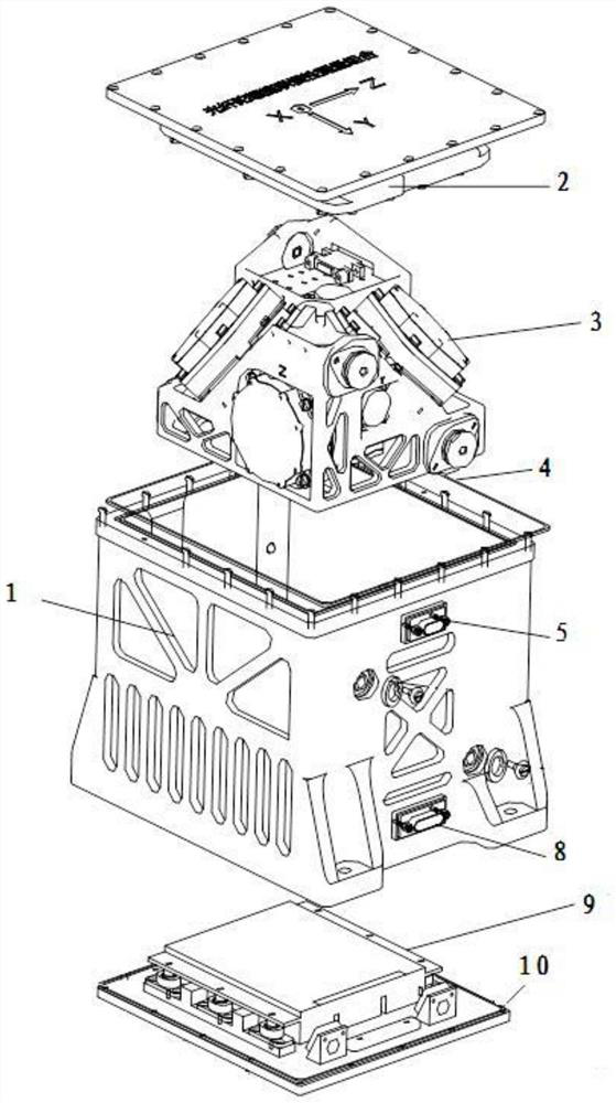
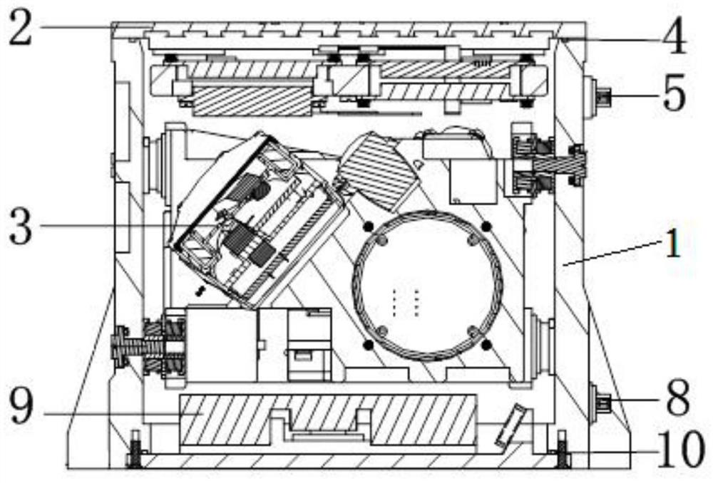
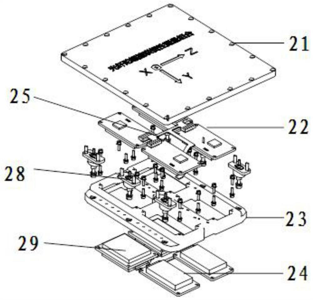
[0032] The invention provides a five-axis redundant optical fiber gyro measuring device structure, which adopts five-way inertial instruments and five-way accelerometers to work independently and redundantly configure each other, rationally use the space, and has the advantages of small size, light weight, good heat dissipation, easy assembly Good workmanship and other advantages. The invention adopts a square box to carry a system circuit, a power supply, and three independent instruments to realize a multi-section layout in one box; the connection of each partition is connected by a relay electrical connector, which facilitates independent assembly of each partition and improves assembly efficiency ; The present invention adopts a ten-meter integrated structure design, which is convenient for centralized vibration reduction and heat insulation of high-precision instruments; ration...


PUM


Abstract

The invention relates to a five-axis redundant fiber-optic gyroscope measuring device structure, and belongs to the technical field of inertial measurement. The structure comprises a box body, a system circuit assembly, an instrument assembly, an upper cover conductive sealing ring, a first sealing connector, a second sealing connector, a power supply assembly and a bottom cover conductive sealing ring, wherein the upper cover conductive sealing ring is arranged at the top opening of the box body; the instrument assembly is arranged in the inner cavity of the box body; the system circuit assembly is installed at the top opening of the box body; the bottom cover conductive sealing ring is arranged around the top end of the power supply assembly; the power supply assembly is in butt joint with the bottom opening of the box body; the first sealing connector and the second sealing connector are arranged on the same side wall of the box body; and the first sealing connector is located above the second sealing connector. According to the invention, five inertial instruments and five accelerometers work independently and are in redundant configuration, the space is utilized reasonably, and the structure has the advantages of small size, light weight, good heat dissipation, good assembly manufacturability and the like.

Description

technical field [0001] The invention belongs to the technical field of inertial measurement and relates to a structure of a five-axis redundant optical fiber gyro measurement device. Background technique [0002] With the development of integrated navigation technology, strapdown inertial group / inertial navigation is playing an increasingly important role in the field of navigation due to its advantages of low cost and easy maintenance, and the requirements for the accuracy and reliability of inertial sensors are also increasing. [0003] Optical fiber gyro is a new type of all-solid-state sensor that uses optical fiber sensing technology to measure space inertial rotation. It has the advantages of high precision, high reliability, and long life. application. [0004] However, most of the existing fiber optic gyroscope inertial measurement modules adopt a three-axis design scheme, and there is no redundant design of inertial instruments. When any one of the axes fails, it c...

Claims


Application Information

Patent Timeline
Patent Type & Authority Applications(China)
IPC IPC(8): G01C19/72
CPCG01C19/72G01C19/721
Inventor 袁韬冯文龙王宁张称称雷剑王嘉铭杨克成左明璐赵婷婷
Owner BEIJING AEROSPACE TIMES OPTICAL ELECTRONICS TECH
Learn More