Hydraulic control device with power supply circuit

A technology of power supply circuit and hydraulic control, which is applied in the direction of valve operation/release device, flow control of electric device, valve device, etc. problem, to achieve the effect of easy installation

Active Publication Date: 2021-10-15
衡阳泰豪通信车辆有限公司
View PDF6 Cites 0 Cited by
  • Summary
  • Abstract
  • Description
  • Claims
  • Application Information

AI Technical Summary

Problems solved by technology

The problem is that most of the main components are foreign brands, which cannot meet the requirements of localization
[0007] 4. In the specific connection process between the chip and the sensor wire in the background technology, the wire generally extends along the wire groove provided on the valve body or the electrical box, but for For the irregular valve body and the electrical box wall in the form of a square plate, its irregular or relatively large volume is not conducive to slotting, or requires a large-scale processing platform
[0008] 5. In the specific installation process of the chip and the sensor wire in the background technology, the wire is laid to the corresponding

Method used


Image

  • Hydraulic control device with power supply circuit
  • Hydraulic control device with power supply circuit
  • Hydraulic control device with power supply circuit

Examples


Embodiment Construction

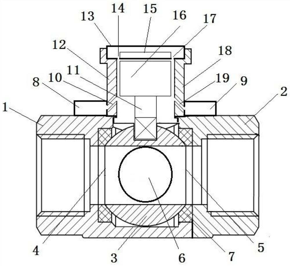
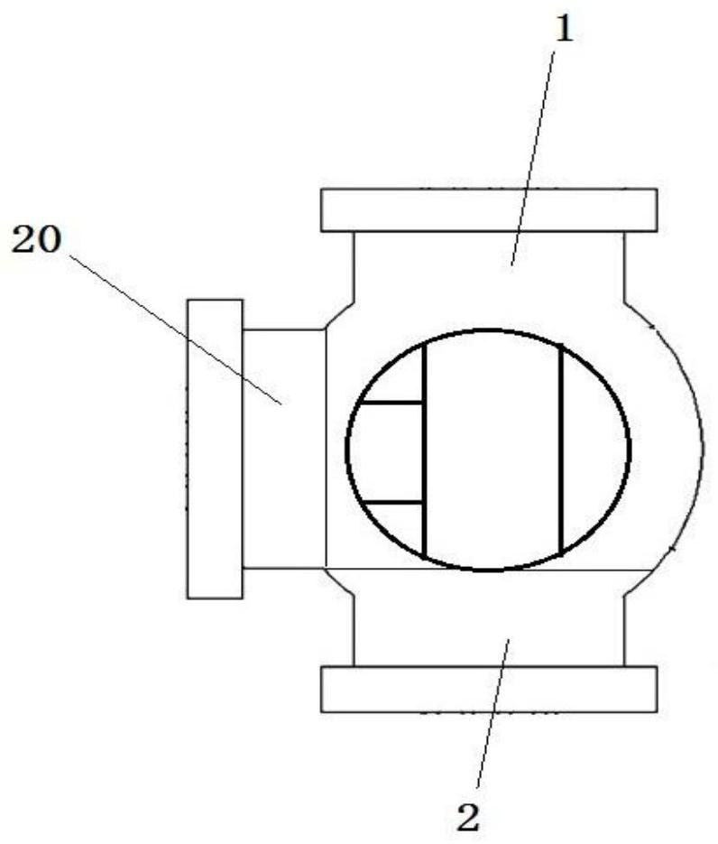
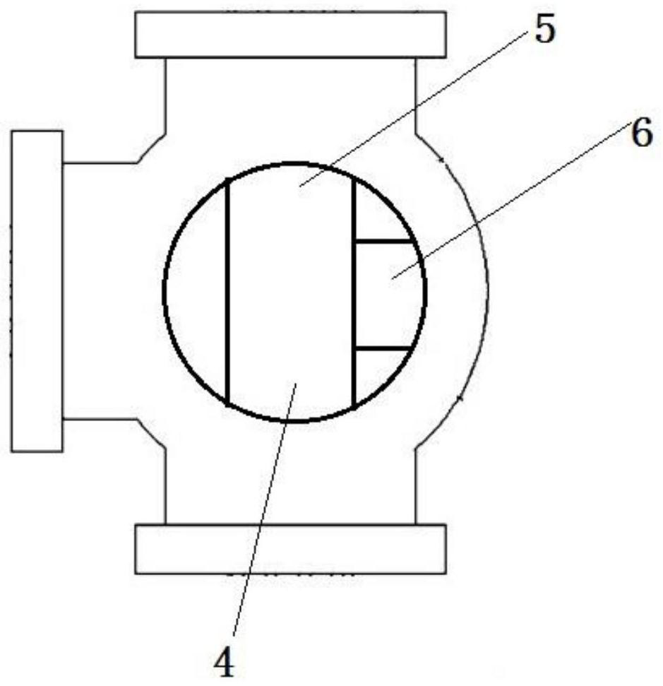
[0047] As shown in the figure: a hydraulic control device with a power supply circuit, including a first distribution valve body, a second distribution valve body, an inflow valve body, a valve core, a sealing seat, a first sensing module, a second sensing module, Drive shaft, bar, electrical box, control board, motor, power supply circuit; wherein the valve core includes a first distribution channel, a second distribution channel, an inflow channel, half valve core one, half valve core two, upper embedded ring, The lower embedded ring, the docking surface, the middle cavity, the inflow check valve, the distribution check valve 1, the distribution check valve 2, the upper positioning plate, and the lower positioning plate; The lower wall is provided with two sections of holes;

[0048] As shown in the figure: the control board and the power supply circuit are provided inside the electrical box, the power supply circuit supplies power to the control board, and the power supply ...


PUM


Abstract

A hydraulic control device with a power supply circuit comprises a first distribution valve body, a second distribution valve body, an inflow valve body, a valve element, a sealing seat, a first sensing module, a second sensing module, a transmission shaft, a strip plate, an electrical box, a control panel and the power supply circuit; the control panel and the power supply circuit are arranged in the electrical box, the power supply circuit supplies power to the control panel, the power supply circuit comprises a main power supply interface, an auxiliary power supply interface, a first voltage stabilizer, a second voltage stabilizer and a safety element, the main power supply interface is connected with the first voltage stabilizer, and a first capacitor is arranged between the power supply input end and the grounding end of the first voltage stabilizer.

Description

technical field [0001] The invention relates to the field of military control vehicle equipment and electronic chips (international classification number H01), in particular to a hydraulic control device with a power supply circuit. Background technique [0002] The main task of centralized management and control equipment is to conduct centralized management, real-time monitoring and comprehensive control of various states and information of public platform equipment. The controlled objects include automobile chassis, information calendar, electric lifting rod, fuel heater, lodging mechanism, Air conditioner, generator set, power wall box, integrated power supply, etc. At present, especially in the field of military use, the requirements for localization and independent control of electronic components such as chips are becoming more and more stringent. The core circuit boards or core electronic components used in centralized control equipment are basically foreign brands. ...

Claims


Application Information

Patent Timeline
IPC IPC(8): F16K11/10F16K15/18F16K27/06F16K31/04F16K37/00G05D7/06
CPCF16K11/10F16K27/067F16K31/042F16K37/0091G05D7/0635
Inventor 潘庭发肖卫卫邓连辉熊奋超冯非易雷军费俭平吕文忠
Owner 衡阳泰豪通信车辆有限公司
Why Eureka
Try Eureka