
Load access detection method and device

A detection device and access terminal technology, applied in the field of load access detection devices, can solve problems such as safety hazards, electric shocks, and existence, and achieve the effects of low construction cost, small size, and not easy to age

Inactive Publication Date: 2021-10-08
四川凭跃科技有限公司
View PDF0 Cites 1 Cited by
  • Summary
  • Abstract
  • Description
  • Claims
  • Application Information

AI Technical Summary

Problems solved by technology

[0003] The existing leakage protector has the following disadvantages: 1. The leakage protector needs to be closed before it can supply power to the terminal, and under normal circumstances, the leakage protector remains closed, so that the voltage at the terminal is the mains voltage. Touching the live wire will cause electric shock, and there are always potential safety hazards
2. The leakage protector will only be automatically disconnected in the case of overcurrent, leakage, etc., that is, first connect the load to the mains and then judge the current size, and then disconnect when the overcurrent occurs, there is still the risk of fire caused by overcurrent

Method used


Image

  • Load access detection method and device
  • Load access detection method and device
  • Load access detection method and device

Examples


Embodiment 1

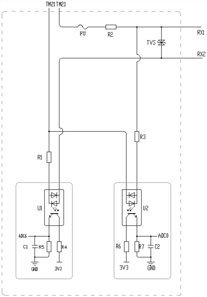
[0032] Load access detection device, see attached figure 1 , Including a DC terminal, a first AC terminal, a second AC terminal, a startup detection module, a short-circuit detection module, and a processor module.

[0033] The startup detection module includes a first bidirectional light coupling U1, and the first bidirectional light-coupled U1 is connected to the direct current terminal, the first bidirectional electrocounted light-coupled U1's output terminus of the controller of the processor Module. The first AC terminal ends one end of the light-shifting source of the first bidirectional light coupling U1 through the first pull-up resistor R1, and the other end of the first bidirectional light coupling U1 is connected to the second load access terminal Rx2.

[0034] The short-circuit detection module includes a second bidirectional light coupling U2, and the second bidirectional isolation optocoupler U2 is input to the direct current terminal, the second bidirectional electr...

Embodiment 2

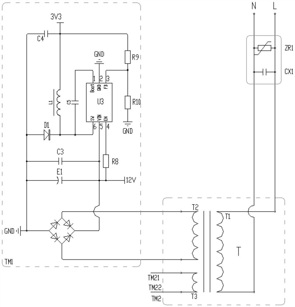
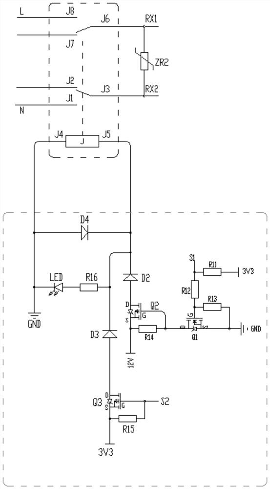
[0037] Load access detection device, see attached figure 1 , 2 , Including primary transformer module TM1, secondary transformer module TM2, start detection module, short circuit detection module, and processor module.

[0038] After the 220V / 360V market is input to the clamp resistance Zr1 clamp and the input filter capacitor Cx1 filtering, the primary coil T1 of the transformer T is connected to the primary coil T2 of the primary transformer TM1 to enter the primary secondary coil T2 of the transformer T, output 3.3 V-level voltage signal provides a DC power supply for the device.

[0039] The start detection module includes a first bidirectional optical coupling U1, and the first pull-up resistor R4 is connected to the input of the first two-way isolation optocoupler U1, the first bidirectional isolation optocoupler U1 The terminal is grounded through the second pull-up resistor R5, and the voltage signal ADC6 between the receiver of the first bidirectional photocoupler U1 an...

Embodiment 3

[0046] This example discloses a load access detecting device, the load access detecting device is similar to the load access detecting device in the second embodiment, and the only difference is that in the present embodiment, the primary secondary coil T2 and the secondary are disclosed. The secondary coil T3 variable ratio is the same, and the market electricity pressure is electrically converted to an alternating current.


PUM


Abstract

The invention discloses a load access detection method and device. The input end of a light receptor of the first bidirectional isolation optocoupler is connected with the direct current terminal, and the output end is connected with the processor module; the first AC terminal is connected with one end of a luminous source of a first bidirectional isolation optocoupler through a first pull-down resistor, and the other end of the luminous source of the first bidirectional isolation optocoupler is connected with a second load access end; the input end of a light receptor of the second bidirectional isolation optocoupler is connected with the direct current terminal, and the output end is connected with the processor module; the first AC terminal is connected with one end of a luminous source of the second bidirectional isolation optocoupler, the second AC terminal is connected with the first load access end through the first divider resistor, and the other end of the luminous source of the second bidirectional isolation optocoupler is connected between the first divider resistor and the first load access end through the first current limiting resistor. When a load is connected, the first bidirectional isolation optocoupler outputs current, the current output by the second bidirectional isolation optocoupler changes, and load connection, short circuit and overcurrent can be detected by detecting the two currents.

Description

Technical field [0001] The present invention relates to the field of overcurrent protector, in particular a load access detecting device and a load access detection method. Background technique [0002] In the existing civilian building, almost 220V / 360V mains, and use leakage protector centralized management of electrical equipment, the main electricity access leakage protector, and then connected by the leakage protector to connect to each end The city electricity is connected directly to the end through the leakage protector. Each end is independent, and when a short circuit, leakage, power is turned off at an end, and the leakage protector is turned off, and the power supply to all ends is stopped. [0003] The existing leakage protector has the following: 1. After the leakage protector needs to be closed, it can supply power to the end, and under normal circumstances, the leakage protector holds a closed state, so that the voltage at the end is the mains, biological touch....

Claims


Application Information

Patent Timeline
Patent Type & Authority Applications(China)
IPC IPC(8): G01R31/52
CPCG01R31/52
Inventor 付光华
Owner 四川凭跃科技有限公司
Learn More