
Structure for preventing lubricating oil coking and leakage deflagration at inter-turbine casings

A technology for handling lubricating oil and turbine, which is applied in the structural field of preventing lubricating oil coking and leakage and deflagration at the casing between turbines

Inactive Publication Date: 2021-10-01
AECC SHENYANG ENGINE RES INST
View PDF2 Cites 2 Cited by
  • Summary
  • Abstract
  • Description
  • Claims
  • Application Information

AI Technical Summary

Problems solved by technology

[0005] The purpose of this application is to provide a structure to prevent coking of lubricating oil and leakage deflagration at the casing between turbines, so as to solve or alleviate at least one problem in the background technology

Method used


Image

  • Structure for preventing lubricating oil coking and leakage deflagration at inter-turbine casings
  • Structure for preventing lubricating oil coking and leakage deflagration at inter-turbine casings
  • Structure for preventing lubricating oil coking and leakage deflagration at inter-turbine casings

Examples


Embodiment Construction

[0047] In order to make the purpose, technical solution and advantages of the application more clear, the technical solution in the embodiment of the application will be described in more detail below in conjunction with the drawings in the embodiment of the application.

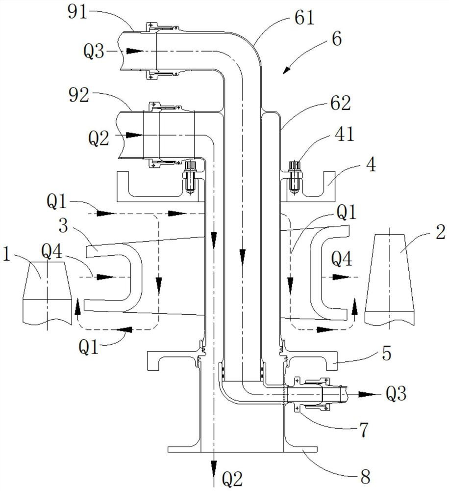
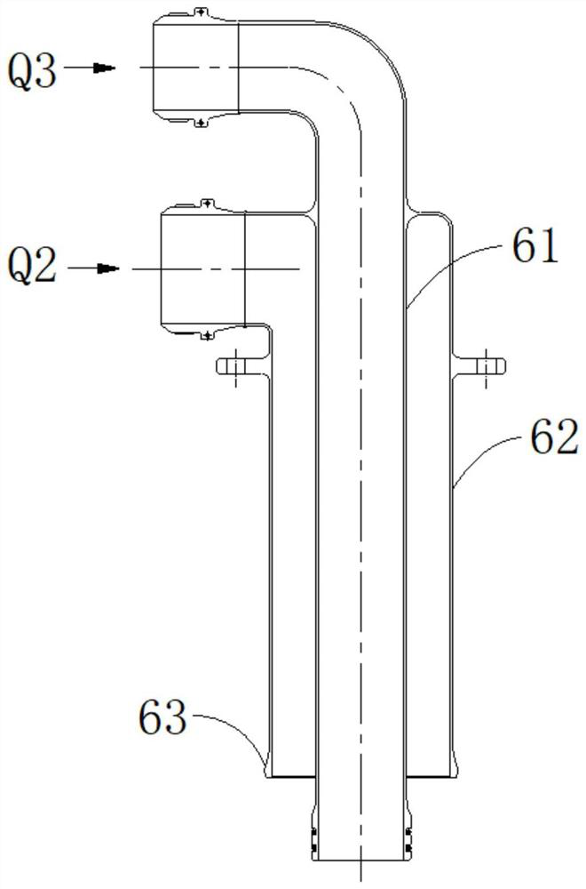
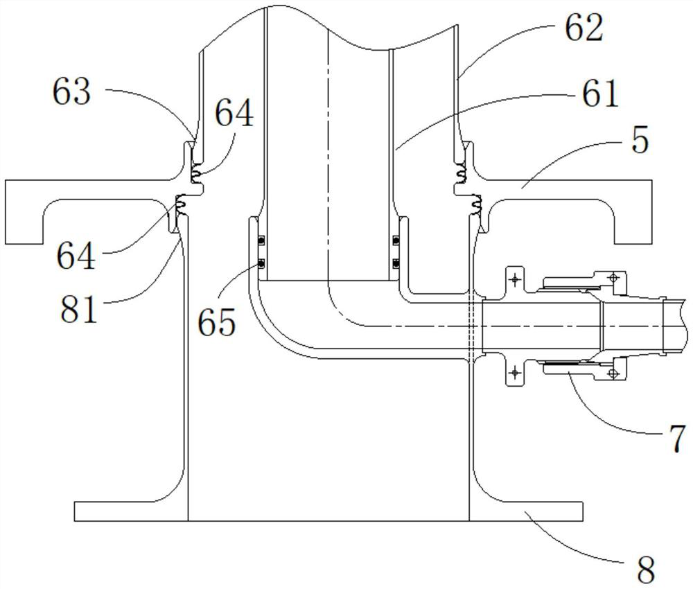
[0048] Such as Figure 1 to Figure 3 As shown, the structure provided by the present application to prevent lubricating oil coking and leaking deflagration at the casing between turbines is mainly realized by using a double-layer isolated combined pipe joint 6, and the structure mainly includes:

[0049] The high-pressure turbine 1 and the low-pressure turbine 2, between the high-pressure turbine 1 and the low-pressure turbine 2, flow the ultra-high temperature main channel gas Q4;

[0050] Between the high-pressure turbine 1 and the low-pressure turbine 2, an inter-turbine casing is arranged, that is, the outer casing 4 between the turbines and the inner casing 5 between the turbines, and the rectifying gui...


PUM


Abstract

The invention provides a structure for preventing lubricating oil coking and leakage deflagration at inter-turbine casings. The structure comprises a high-pressure turbine, a low-pressure turbine, an inter-turbine outer casing, an inter-turbine inner casing, an isolation type combined pipe joint, a bearing cavity oil supply pipe joint and an outlet flow distribution joint, wherein main runner gas circulates between the high-pressure turbine and the low-pressure turbine; the inter-turbine outer casing and then inter-turbine inner casing are arranged between the high-pressure turbine and the low-pressure turbine, rectification blades are arranged between the high-pressure turbine and the low-pressure turbine, and main runner sealing gas circulates in the rectification blades; the isolation type combined pipe joint penetrates through the rectification blades in a main runner to be connected with the inter-turbine outer casing and the inter-turbine inner casing, the isolation type combined pipe joint is provided with an inner oil supply pipe and an outer sealing gas guide pipe, the inner oil supply pipe is used for circulating lubricating oil, the outer sealing gas guide pipe is used for circulating bearing cavity sealing gas, and the outer sealing gas guide pipe is located on the outer layer of the inner oil supply pipe, and therefore, the bearing cavity sealing gas circulating in the outer sealing gas guide pipe enables the main runner sealing gas in the rectification blades and the lubricating oil in the inner oil supply pipe to form a heat insulation state; and the bearing cavity oil supply pipe joint is connected with the inner oil supply pipe, and the outlet flow distribution joint is connected with the outer sealing gas guide pipe.

Description

technical field [0001] The application belongs to the technical field of aero-engines, and in particular relates to a structure for preventing lubricating oil coking and leaking deflagration at the inter-turbine casing. Background technique [0002] During the working process of an aero-engine, the high and low pressure rotors need to use bearings and stator casings to transmit loads to each other, and most bearings need lubricating oil to lubricate during work, but lubricating oil is easy to coke and leak when encountering high temperature environments. When the lubricating oil is in direct contact with high-temperature gas, there is a risk of deflagration of the lubricating oil. Severe coking and deflagration will pose a threat to the safe operation of the aero-engine. [0003] At the same time, most aero-engines arrange inter-turbine casings between the high-pressure and low-pressure turbines. In order to suppress the incongruity of thermal deformation of the force-transf...

Claims


Application Information

Patent Timeline
Patent Type & Authority Applications(China)
IPC IPC(8): F02C7/06F02C7/24F02C7/28F01D25/18F01D25/08F01D11/04
CPCF02C7/06F02C7/24F02C7/28F01D25/18F01D25/08F01D11/04
Inventor 怀时卫金海周建超周伟朋
Owner AECC SHENYANG ENGINE RES INST
Learn More