
Multi-step multi-contour coating forming reaming and milling cutter

A multi-contour, multi-step technology, applied in the field of processing tools, can solve the problems of poor coaxiality, high processing cost, and milling cutter breakage, etc., to save processing time and tool setting time, and enhance support and firmness, and the effect of improving the accuracy of shape and position tolerances

Pending Publication Date: 2021-10-01
JIANGMEN JUNJIE TOOL TECH CO LTD
View PDF16 Cites 0 Cited by
  • Summary
  • Abstract
  • Description
  • Claims
  • Application Information

AI Technical Summary

Problems solved by technology

[0005] The machining of stepped holes is mainly carried out in the form of a combination of an alloy drill bit and an end mill. First, the alloy drill bit is used to rough-machine the small-diameter hole and the large-diameter hole in sequence, and then the end mill is used to finish the small-diameter hole and the large-diameter hole in sequence. The above-mentioned method of processing different-diameter holes not only takes a long time, but also frequently replaces the tool, resulting in large shape and position tolerances between the two step surfaces, poor coaxiality, low processing accuracy, and high processing costs.
[0006] In order to improve the processing efficiency, there are common conventional step milling cutters in the market to process the step holes at one time, but there is a risk of serious cutter breakage and increased scrap rate, which makes the production cost high

Method used


Image

  • Multi-step multi-contour coating forming reaming and milling cutter
  • Multi-step multi-contour coating forming reaming and milling cutter
  • Multi-step multi-contour coating forming reaming and milling cutter

Examples


Embodiment Construction

[0025] The specific implementation manners of the present invention will be further described in detail below in conjunction with the accompanying drawings and embodiments. The following examples are used to illustrate the present invention, but are not intended to limit the scope of the present invention.

[0026] In describing the present invention, it is to be understood that the terms "upper", "lower", "left", "right", "front", "rear", "top", "bottom" etc. indicate an orientation or position The relationship is based on the orientation or positional relationship shown in the drawings, and is only for the convenience of describing the present invention and simplifying the description, rather than indicating or implying that the machine or element referred to must have a specific orientation, be constructed and operated in a specific orientation, therefore It should not be construed as a limitation of the present invention. It should be understood that the terms "first", "s...


PUM


Abstract

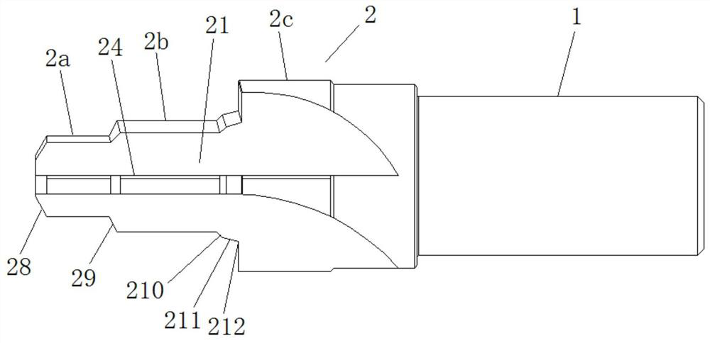
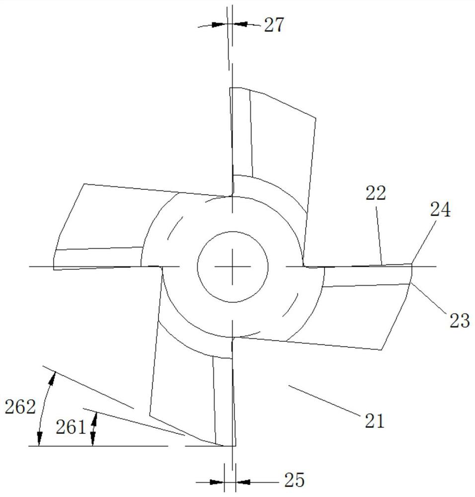
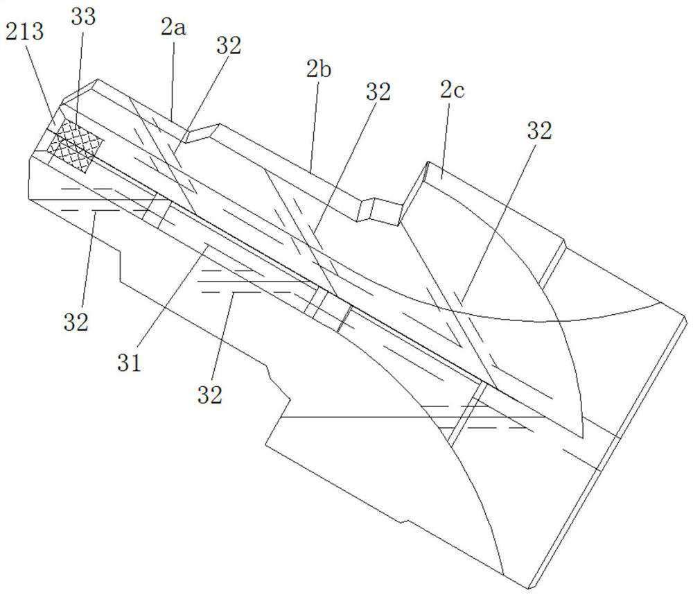
The invention discloses a multi-step multi-contour coating forming reaming and milling cutter. The cutter comprises a handle part and a stepped cutting part, the stepped cutting part is provided with four stepped cutter grooves axially extending from the front end of the stepped cutting part to the handle part, the faces, facing the cutting rotation direction, of the stepped cutter grooves are front cutter faces, and the faces, back to the cutting rotation direction, of the stepped cutter grooves are rear cutter faces. The front cutter faces and the rear cutter faces intersect to form circumferential cutting edges, the outer diameter of the stepped cutting part is increased in a stepped mode from the front end of the stepped cutting part to the handle part, and the stepped cutting part is provided with a first-stage cutting part, a second-stage cutting part and a third-stage cutting part in sequence from small to large; the circumferential cutting edge on the first-stage cutting part is provided with a first arc edge belt with the width of 0.4 mm-0. 45 mm and a plurality of first rear angles; the circumferential cutting edge on the second-stage cutting part is provided with a second arc edge belt with the width of 0.7 mm-0. 9 mm and a plurality of second rear angles; and the circumferential blade on the third-stage cutting part is provided with a third arc edge belt with the width of 1 mm-1.3 mm and a plurality of third rear angles. The cutter has the beneficial effects of multiple purposes, high efficiency, long service life and high precision.

Description

technical field [0001] The invention belongs to the technical field of processing tools, in particular to a multi-step and multi-contour coating forming milling reamer. Background technique [0002] A milling cutter is a rotating tool with one or more teeth for milling. When working, each knife tooth cuts off the allowance of the workpiece intermittently in turn. Milling cutters are mainly used for machining planes, steps, grooves, forming surfaces and cutting off workpieces on milling machines. [0003] Milling cutters can be further divided into cylindrical milling cutters, face milling cutters, end mills, three-sided milling cutters, angle milling cutters, saw blade milling cutters and T-shaped milling cutters according to their uses. According to the assembly form of milling cutter and cutter body, milling cutters can be divided into integral milling cutters, integral welding tooth milling cutters, insert tooth milling cutters, and indexable milling cutters. [0004] ...

Claims


Application Information

Patent Timeline
Patent Type & Authority Applications(China)
IPC IPC(8): B23C5/10B23C5/16B23C5/28
CPCB23C5/10B23C5/16B23C5/28
Inventor 咸志鹏
Owner JIANGMEN JUNJIE TOOL TECH CO LTD
Learn More