Quick dismounting device and method for cotter pin

A dismantling device and cotter pin technology, which is applied to hand-held tools, manufacturing tools, etc., can solve the problems of easy damage to nuts and other parts, lack of quick disassembly methods, and difficulty in disassembly by ordinary tools, so as to improve operational stability and speed. The effect of dismantling and reducing the difficulty of operation

Active Publication Date: 2021-09-24
CHENGDU AIRCRAFT INDUSTRY GROUP
View PDF5 Cites 0 Cited by
  • Summary
  • Abstract
  • Description
  • Claims
  • Application Information

AI Technical Summary

Problems solved by technology

However, after the cotter pin is installed, it is tightly connected with the nut, so it is difficult to disassemble it with ordinary tools
When repairing or reinstalling the cotter pin is required, the original cotter pin is difficult to disassemble safely, and the nut and other parts are easily damaged during the disassembly process
[0004] At the same time, due to the current general-purpose tools such as needle-nose pliers and flat-nose pliers, in order not to damage the parts, although the clamping area is provided with anti-skid lines, the lines are relatively shallow, especially the cotter pins are semicircular, and the force-bearing area is narrow. , so it is more difficult to clamp, easy to slide, fall off, and cause damage to the nut
[0005] To sum up, in the field of cotter pin installation and disassembly, there is still a lack of a small size, simple structure, easy to operate, easy to carry disassembly device and corresponding quick disassembly method

Method used


Image

  • Quick dismounting device and method for cotter pin
  • Quick dismounting device and method for cotter pin
  • Quick dismounting device and method for cotter pin

Examples


Embodiment 1

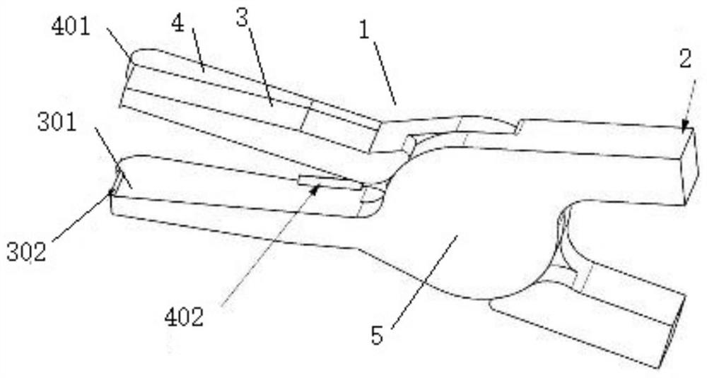
[0043] A cotter pin quick release device such as Figure 1-Figure 4 As shown, it includes two clamping parts 1 that are movable riveted with each other, each of the clamping parts 1 includes a clamping area and a gripping area 2 connected with the clamping area, and the clamping area includes a clamping part 3 and The support member 4, the clamping member 3 and the support member 4 are on the same horizontal plane;

[0044] The clamping member 3 includes a clamping end 301 and a first connecting end, the first connecting end is connected to the gripping area 2 , and the end of the clamping end 301 is provided with a clamping edge 302 .

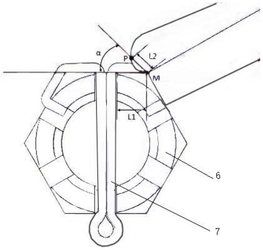
[0045] The support member 4 includes an arc-shaped support end 401 and a second connection end. The clamping end 301 and the arc-shaped support end 401 are connected side by side to form a connection point. The angle formed between is identical with the included angle of nut 6;

[0046] One of the support members 4 is also provided with a ja...

Embodiment 2

[0065] A method for quick disassembly of cotter pins, comprising the following steps:

[0066] (1) Bending the cotter pin in reverse: the clamping edges 302 of the two clamping parts 3 in the quick release device of the cotter pin 7 clamp the tail of the cotter pin 7 wound on the end face of the nut 6, and the arc of the supporting part 4 The support end 401 is supported by the end surface of the other end of the nut 6, rotates according to the arc of the arc-shaped support end 401, reversely bends the tail of the cotter pin 7, and restores the tail of the cotter pin 7 from a tightly installed state to a free open state;

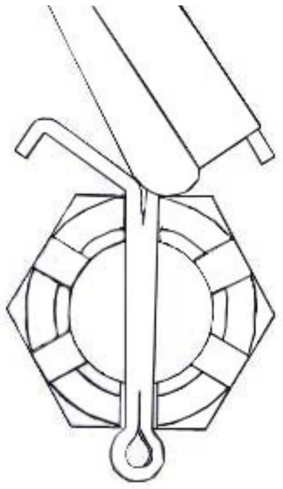
[0067] (2) Rotate the cotter pin: Use the cotter pin 7 quick release device to clamp the tail of the cotter pin 7, and rotate the cotter pin 7 around its own axis by 90°; the 90 ° rotation is mainly to facilitate the cotter pin 7 quick disassembly device to align the cotter pin The cotter pin 7 tail of 7 is cut;

[0068] (3) Trimming the cotter pin: Utilize...


PUM


Abstract

The invention discloses a quick dismounting device and method for a cotter pin, and belongs to the field of assembly. The quick dismounting device comprises two clamping parts which are movably riveted with each other. Each clamping part comprises a clamping area and a holding area connected with the clamping area, each clamping area comprises a clamping piece and a supporting piece, and the clamping pieces and the supporting pieces are located on the same horizontal plane. Each clamping piece comprises a clamping end, wherein a clamping cutting edge is arranged at the end portion of the clamping end, and each supporting piece comprises an arc-shaped supporting end. The clamping cutting edges are additionally arranged at the end portions of the clamping parts, the clamping cutting edges are partially sunken into the tail of the cotter pin under the action of clamping force, the cotter pin can be effectively clamped, deformation and dislocation of the cotter pin in the disassembling process are avoided, and the cotter pin is prevented from sliding and loosening in the clamping process. A jaw is additionally arranged and can pinch off the tail part of the opened cotter pin, so that the residual cotter pin forms a barrier-free pin, the cotter pin is conveniently pulled out, a nut and a bolt are not damaged, and the disassembly is quicker after direct pulling.

Description

technical field [0001] The invention relates to the field of assembly, in particular to a quick disassembly device and method for a cotter pin, which is mainly used in the disassembly process of cotter pins in various electromechanical equipment and systems. Background technique [0002] Cotter pin is a kind of metal hardware, commonly known as spring pin, safety pin, and also a mechanical part, mainly used for threaded connection and anti-loosening. After tightening the nut, insert the split pin into the nut groove and the hole at the end of the bolt, and pull the tail of the split pin apart to prevent the relative rotation between the nut and the bolt. [0003] For ordinary use occasions, it is enough to open the cotter pin to 60°, which can meet the anti-loosening requirements, and the installation work can be completed by using ordinary screwdrivers and wrenches. However, for fields with high reliability requirements such as aviation and aerospace equipment, it is neces...

Claims


Application Information

Patent Timeline
IPC IPC(8): B25B27/00
CPCB25B27/00
Inventor 何磊刘雪豪张开剑曹虎钟学敏张领伟谭与龙刘云飞王向凯
Owner CHENGDU AIRCRAFT INDUSTRY GROUP
Why Eureka
Try Eureka