
Stripping device for alloy plate stamping die

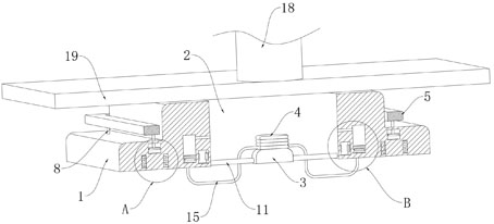
A technology for stamping dies and alloy sheets, which is applied in the field of stripping devices for stamping dies for alloy sheets, can solve problems such as low safety, damage to stamping parts, worker injuries, etc., and achieve the effects of improving safety performance, preventing damage and long service life

Active Publication Date: 2021-09-24
南通维益机电有限公司
View PDF5 Cites 0 Cited by
  • Summary
  • Abstract
  • Description
  • Claims
  • Application Information

AI Technical Summary

Problems solved by technology

[0002] In the process of sheet metal processing, it is often necessary to punch holes in the sheet metal. Due to the low efficiency of traditional drilling, stamping is often used for punching, and stamping parts or stamping edge materials often get stuck during the punching process. Phenomenon, inconvenient to take out
[0003] In order to solve this problem, the application number is "201811174586.8" and "a stamping die dragging device and its use method" is proposed. This solution sets wedges, springs, push buttons and other components. After the stamping is completed, by operating the push button, Use the elastic force of the spring to move the dragging frame up to push out the stamping parts. In the process of using this method, not only it is very troublesome to manually press the button frequently, but also because the physical coordination of each person is different, if the worker presses There is a difference between the rhythm of pressing the button and the falling rhythm of the punching head. It is very easy for workers to press the button when the punching head is falling, which will not only cause damage to the stamping parts, but also cause injury to the workers, and the safety is low.

Method used


Image

  • Stripping device for alloy plate stamping die
  • Stripping device for alloy plate stamping die
  • Stripping device for alloy plate stamping die

Examples


Embodiment Construction

[0019] The following will clearly and completely describe the technical solutions in the embodiments of the present invention with reference to the accompanying drawings in the embodiments of the present invention. Obviously, the described embodiments are only some, not all, embodiments of the present invention.

[0020] In describing the present invention, it should be understood that the terms "upper", "lower", "front", "rear", "left", "right", "top", "bottom", "inner", " The orientation or positional relationship indicated by "outside", etc. is based on the orientation or positional relationship shown in the drawings, and is only for the convenience of describing the present invention and simplifying the description, rather than indicating or implying that the referred device or element must have a specific orientation, so as to Specific orientation configurations and operations, therefore, are not to be construed as limitations on the invention.

[0021] refer to Figure ...


PUM


Abstract

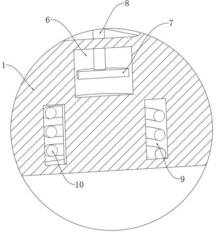
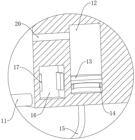
The invention discloses a stripping device for an alloy plate stamping die. The stripping device comprises a fixed die plate, a punched hole is formed in the fixed die plate, the fixed die plate is provided with a top frame in a sleeving mode, a pushing device for pushing the top frame to move is installed on the fixed die plate, and the pushing device comprises a magnetic plate, an ejector rod, a magnet exciting coil and a power supply mechanism; the power supply mechanism is used for supplying power to the magnet exciting coil and comprises a vibration power generation piece, a buffering air bag, an air guide pipe, a capacitor and a control mechanism; and the control mechanism is used for controlling on and off of a circuit, and the control mechanism comprises a conducting ring and a conducting strip. By arranging the pushing device, kinetic energy generated when a stamping head falls down can be used for driving the pushing device to operate, so that when the stamping head is lifted, the top frame can be automatically moved upwards and a stamped plate is ejected out, the stamped plate is prevented from being clamped, meanwhile, manual operation is not needed, and the safety performance of the device is greatly improved.

Description

technical field [0001] The invention relates to the related technical field of plate stamping equipment, in particular to a stripping device for an alloy plate stamping die. Background technique [0002] In the process of sheet metal processing, it is often necessary to punch holes in the sheet metal, but due to the low efficiency of traditional drilling, stamping is often used for punching, and stamping parts or stamping edge materials often get stuck during the punching process Phenomenon, inconvenient to take out. [0003] In order to solve this problem, the application number is "201811174586.8" and "a stamping die dragging device and its use method" are proposed. The solution sets wedges, springs, push buttons and other components. After the stamping is completed, by operating the push button, Use the elastic force of the spring to move the dragging frame up to push out the stamping parts. In the process of using this method, not only it is very troublesome to manually...

Claims


Application Information

Patent Timeline
Patent Type & Authority Applications(China)
IPC IPC(8): B21D28/34B21D45/04B21D28/26
CPCB21D28/34B21D45/003B21D45/04B21D28/26
Inventor 姜小波
Owner 南通维益机电有限公司
Learn More