
Industrial equipment waste gas circulating treatment equipment

A waste gas circulation and treatment equipment technology, applied in the direction of dispersed particle separation, chemical instruments and methods, separation methods, etc., can solve environmental impacts, affect human physical and mental health and other problems, and achieve the effect of saving manpower

Pending Publication Date: 2021-09-21
龙南鸿宇泰科技有限公司
View PDF7 Cites 0 Cited by
  • Summary
  • Abstract
  • Description
  • Claims
  • Application Information

AI Technical Summary

Problems solved by technology

[0006] In order to overcome the shortcomings of artificially exhausting the waste gas into a closed space for cooling and liquefaction, and then taking out the waste liquid for sewage treatment, which can not solve the fundamental problem, and has an impact on the environment, and affects the physical and mental health of the artificial during the treatment process, the present invention aims to The technical problem to be solved is to provide an industrial equipment exhaust gas circulation treatment equipment that can reprocess the waste liquid without affecting the environment and does not require manual contact with the waste gas and waste liquid.

Method used


Image

  • Industrial equipment waste gas circulating treatment equipment
  • Industrial equipment waste gas circulating treatment equipment
  • Industrial equipment waste gas circulating treatment equipment

Examples


Embodiment 1

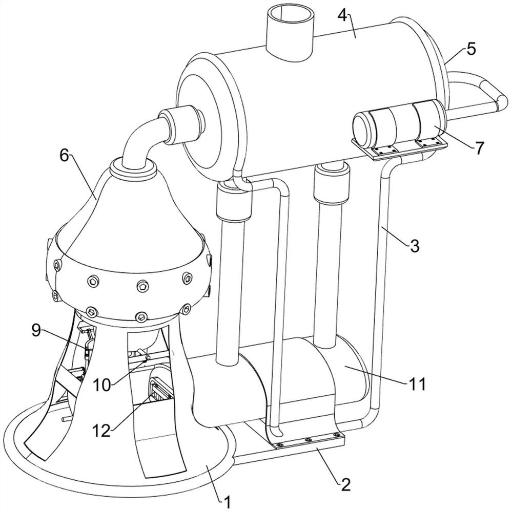
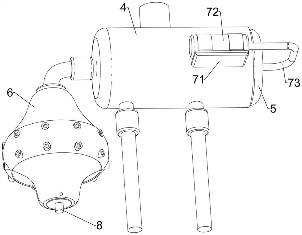
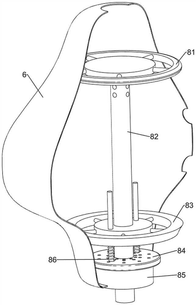
[0036] A kind of industrial equipment exhaust gas circulation treatment equipment, such as Figure 1-3 As shown, it includes a support frame 1, a bottom plate 2, a support rod 3, an exhaust gas bucket 4, a push plate 5, a liquefaction frame 6, a drive assembly 7 and a cooling assembly 8. The left and right sides are connected with support rods 3, and the upper part of the support rods 3 on both sides is connected with the waste gas barrel 4, and the right side of the waste gas barrel 4 is slidingly connected with the push plate 5, and the upper part of the support frame 1 is connected with the liquefaction frame 6, and the liquefaction frame The top of 6 is connected to the left part of the waste gas barrel 4, a one-way switch is provided between the waste gas barrel 4 and the liquefaction frame 6, the front right part of the waste gas barrel 4 is connected to the driving assembly 7, and the inside of the lower part of the liquefaction frame 6 is connected to the cooling assemb...

Embodiment 2

[0041] On the basis of Example 1, such as figure 1 , Figure 4 with Figure 5 As shown, an extruding assembly 9 is also included, and the extruding assembly 9 includes an arc plate 91, a connecting plate 92, a slider 93, an arc splint 94 and a torsion spring 95, and the right side of the lower part of the liquefaction frame 6 is connected with an arc plate 91, the left side of the middle part of the support frame 1 is connected with a connecting plate 92, the middle part of the connecting plate 92 right side is slidably connected with a slide block 93, and the sliding block 93 top is rotatably connected with two arc splints 94, and the arc splint 94 is connected with the arc The plates 91 cooperate, and a torsion spring 95 is connected between the two arc splints 94 .

[0042]When the sponge block 85 moves downward, the two arc splints 94 move to the right by manually pushing the slide block 93 to the right, and the two arc splints 94 move to the right and contact the arc pl...

Embodiment 3

[0044] On the basis of Example 2, such as figure 1 with Figure 6-Figure 9 As shown, a limit assembly 10 is also included, and the limit assembly 10 includes a second spring 101, a first slide bar 102, a wedge block 103, a third spring 104, a first rack 105, a first rotating shaft 106, a first gear 107, the second rotating shaft 108, the second gear 109, the second slide bar 110 and the second rack 111, the second spring 101 is connected between the slider 93 and the connecting plate 92, and the front and rear sides of the upper part of the connecting plate 92 are sliding The first slide bar 102 is connected, and the inside of the first slide bar 102 on both sides is connected with a wedge block 103. The wedge block 103 on both sides cooperates with the slide block 93, and the wedge block 103 on both sides is connected to the connecting plate 92. There is a third spring 104, the first rack 105 is connected to the outside of the wedge block 103 bottom on both sides, the first ...


PUM


Abstract

The invention relates to treatment equipment, in particular to industrial equipment waste gas circulating treatment equipment. The technical problem to be solved by the invention is to provide the industrial equipment waste gas circulating treatment equipment which can retreat waste liquid, does not influence the environment and does not need manual contact with waste gas and waste liquid. The industrial equipment waste gas circulating treatment equipment comprises: a supporting frame which is connected to a bottom plate; a supporting rod which is connected to the bottom plate; a waste gas barrel which is connected to the supporting rod; a push plate which is connected to the waste gas barrel in a sliding manner; a liquefying frame which is connected to the supporting frame, wherein the liquefying frame is connected with the waste gas barrel, and a one-way switch is arranged between the waste gas barrel and the liquefying frame; a driving assembly which is connected to the waste gas barrel; and a cooling assembly which is connected to the liquefying frame. The industrial waste gas is liquefied through the driving assembly and the cooling assembly.

Description

technical field [0001] The invention relates to a processing device, in particular to a recycling processing device for industrial equipment waste gas. Background technique [0002] Industrial waste gas refers to the general term for all kinds of pollutant gases that are discharged into the air during fuel combustion and production processes in the factory area. These substances enter the human body through the respiratory tract in different ways, some directly cause harm, and some have a cumulative effect, which will seriously endanger human health. Different substances will have different effects. [0003] At present, people usually treat industrial waste gas by manually discharging the waste gas into a closed space for cooling and liquefaction, and then taking out the waste liquid for sewage treatment. This treatment cannot solve the fundamental problem, and it will affect the environment. Artificial physical and mental health. [0004] Therefore, it is urgent to desig...

Claims


Application Information

Patent Timeline
Patent Type & Authority Applications(China)
IPC IPC(8): B01D53/00
CPCB01D53/002B01D53/005
Inventor 杨伟宏徐刚
Owner 龙南鸿宇泰科技有限公司
Learn More