
Compression molding mechanical property testing device for loose materials

A technology for pressing and forming loose materials. It is used in measuring devices, using stable tension/pressure to test the strength of materials, scientific instruments, etc. It can solve the problem of inability to measure the stress-strain relationship of materials, low pressing speed, and inability to run continuously, etc. question

Active Publication Date: 2021-09-17
NANJING UNIV OF SCI & TECH
View PDF2 Cites 0 Cited by
  • Summary
  • Abstract
  • Description
  • Claims
  • Application Information

AI Technical Summary

Problems solved by technology

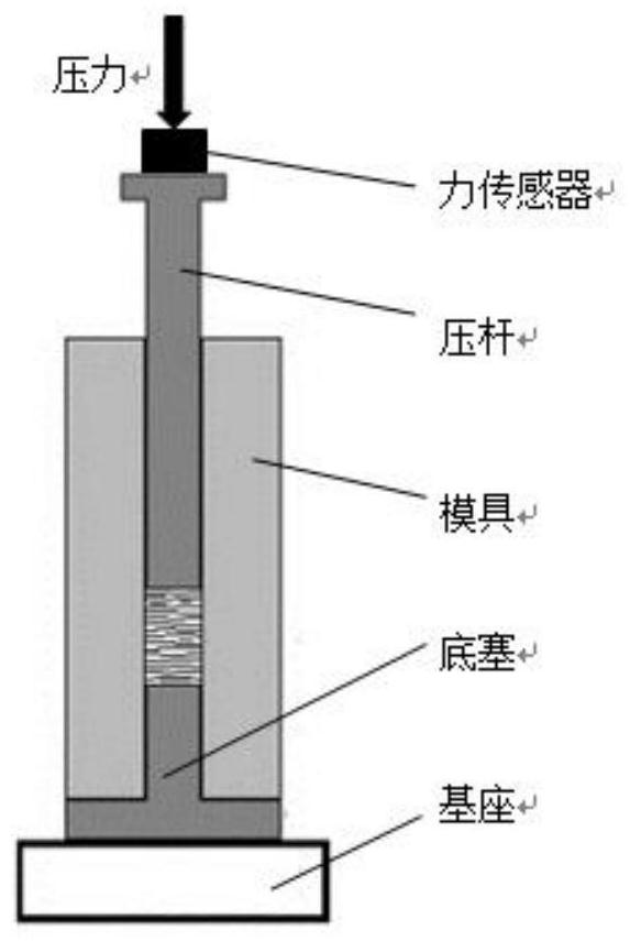
This type of device can only press at a constant speed and measure the force exerted on the pressing rod. The pressing speed is low and the stress-strain relationship of the material during the molding process cannot be tested.
Patent ZL201310629828.9 mentions a multifunctional bulk material forming test device, which cannot realize high-speed pressing close to real working conditions, cannot run continuously, and cannot measure the stress-strain relationship of materials during the pressing process
Patent ZL201710396368.8 mentions a mechanical behavior test device and test method for the compact forming process of loose materials, which can test the stress-strain relationship in the process of forming loose materials, but it needs to be driven by a universal testing machine or a hydraulic cylinder, and the pressing speed It is far lower than the compact forming process of loose materials under actual working conditions, and continuous experiments cannot be carried out, and the collected data cannot accurately reflect the mechanical behavior of the compact forming process of loose materials under actual working conditions

Method used


Image

  • Compression molding mechanical property testing device for loose materials
  • Compression molding mechanical property testing device for loose materials
  • Compression molding mechanical property testing device for loose materials

Examples


Embodiment Construction

[0027] The present invention will be further introduced below in conjunction with the accompanying drawings and specific embodiments.

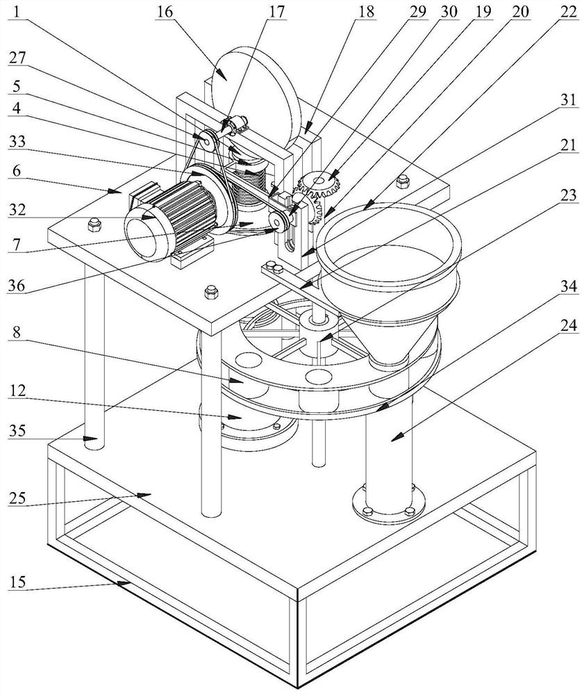
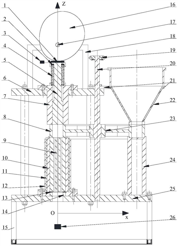
[0028] combine Figure 2-Figure 4 , a loose material compression molding mechanical performance testing device of the present embodiment includes a frame, a driving unit, a pressing unit, a feeding unit, a mold unit, and a cam.

[0029] Described driving unit adopts motor 32, and described pressing unit comprises spring 4, pressing shaft 5, upper base plate 6, upper sleeve 7; Described frame comprises upper base plate 6, upper frame 18, lower frame 15, lower base plate 25.

[0030] A synchronous belt is used for transmission between the motor 32 and the cam 16. The cam 16 is connected to the upper frame 18 by the camshaft 17. The upper base plate 6 and the lower base plate 25 are connected and fixed by a plurality of support columns 35 to ensure that the upper sleeve 7 The coaxiality with the lower sleeve 10 is within a certain range.

[00...


PUM


Abstract

The invention discloses a compression molding mechanical property testing device for a loose material. The device comprises a rack; a hopper used for applying materials into a feeding unit; the feeding unit provided with a plurality of loading rings for receiving materials; a cam used for rotating under the driving of a driving unit to apply pressure to a pressing unit, wherein a gap for accommodating the loading rings is formed between the pressing unit and a mold unit; the pressing unit used for pressing materials in the loading rings into the mold unit; the driving unit connected with the cam and the feeding unit through a first transmission mechanism and a second transmission mechanism respectively; the second transmission mechanism enabling the feeding unit to be separated from the driving unit in the downward moving process of the pressing unit, so that the loading ring located between the pressing unit and the mold unit is in a static state; when the pressing unit moves upwards to the highest position, the second transmission mechanism enabling the feeding unit to be connected with the driving unit so as to complete sequential conveying of the loading rings, so that one-by-one conveying of the loading rings is achieved; a measuring unit used for measuring mechanical parameters. The device is consistent with actual working conditions.

Description

technical field [0001] The invention belongs to the field of compression molding of loose materials designed for feed machinery, biomass energy, powder metallurgy, nuclear fuel pellets, etc., in particular to a mechanical performance testing device for compression molding of loose materials. Background technique [0002] Densification molding process refers to the technology of using molds to compress loose materials into products with regular shape and certain density. It has been widely used in feed and biomass fuel processing, nuclear fuel pellet production, powder metallurgy and other fields. At present, this technology mainly has problems such as unpredictable molding quality and high molding energy consumption, which seriously restricts the development of related industries. In order to solve this problem, relevant scholars at home and abroad have carried out a lot of research, mostly focusing on the influence of raw material characteristics, process parameters and equ...

Claims


Application Information

Patent Timeline
IPC IPC(8): G01N3/08G01N3/06G01N3/02
CPCG01N3/08G01N3/06G01N3/068G01N3/02G01N2203/0019G01N2203/0075G01N2203/0641G01N2203/0676G01N2203/0682
Inventor 王禹孙万峰孙宇武凯丁武学
Owner NANJING UNIV OF SCI & TECH
Learn More