
Resonant converter capable of automatically adjusting frequency and control method thereof

A resonant converter, a technology of resonant conversion, applied in the direction of adjusting electric variable, output power conversion device, converting DC power input to DC power output, etc., can solve the problem of linear adjustment rate difference of 200 in the resonant converter and limit the application of the resonant converter fields, inability to apply automotive electronics, etc.

Active Publication Date: 2021-09-14
CHENGDU MONOLITHIC POWER SYST
View PDF22 Cites 1 Cited by
  • Summary
  • Abstract
  • Description
  • Claims
  • Application Information

AI Technical Summary

Problems solved by technology

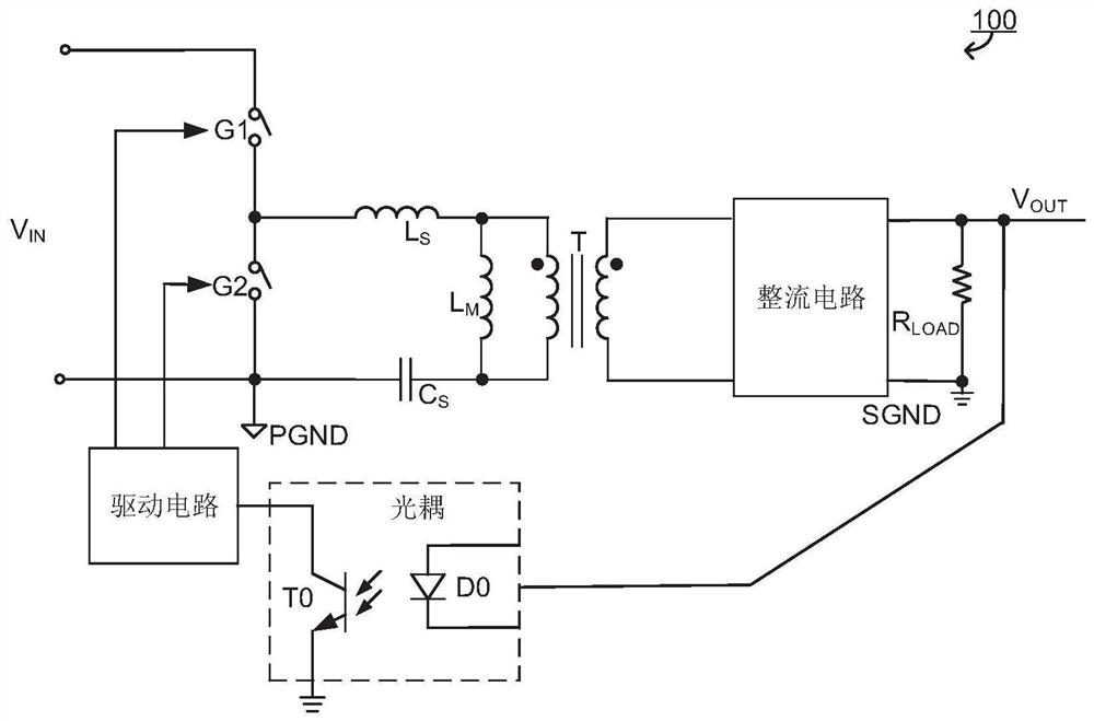
exist figure 1 In the above, the information on the secondary side of the transformer T is fed back to the primary side of the transformer T through the optocoupler, but the use of the optocoupler not only increases the cost of the resonant converter, but also limits the application field of the resonant converter, for example, it cannot be applied to automotive electronics , and other fields requiring high reliability
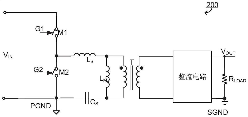
exist figure 2 , the information on the secondary side of the transformer T is no longer fed back to the primary side of the transformer T, so the output voltage V OUT follow the input voltage V IN , the linear regulation of the resonant converter 200 is poor

Method used


Image

  • Resonant converter capable of automatically adjusting frequency and control method thereof
  • Resonant converter capable of automatically adjusting frequency and control method thereof
  • Resonant converter capable of automatically adjusting frequency and control method thereof

Examples


Embodiment Construction

[0024] The specific embodiments of the present invention will be described in detail below. It should be noted that the embodiments described herein are only used for illustration and are not used to limit the present invention. In the following description, numerous specific details are set forth in order to provide a thorough understanding of the present invention. It will be apparent, however, to one of ordinary skill in the art that these specific details need not be employed to practice the present invention. In other instances, well-known circuits, materials, or methods have not been described in detail in order to avoid obscuring the present invention.

[0025] In the description and claims of the present disclosure, if words such as "left, right, inner, outer, upper, lower, upper, lower" are used, they are only for the convenience of description, and do not represent components / / The necessary or permanent relative position of a structure. Those skilled in the art wi...


PUM


Abstract

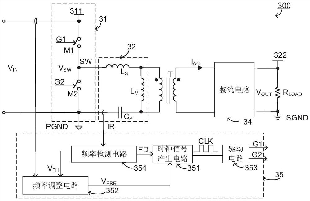
The invention relates to a method for controlling a resonant converter having an input for receiving an input voltage, an output for providing an output voltage, the resonant converter comprising a resonant tank, a switching module, a transformer having a primary side and a secondary side, and a rectifier circuit, wherein the resonant circuit is coupled between the switch module and the primary side of the transformer and has a characteristic resonant frequency, the switching module comprises at least two power switches, the at least two power switches work at a switching frequency to drive the resonant circuit, and the rectification circuit is coupled between the secondary side of the transformer and the output end. The control method includes detecting an input voltage, and adjusting a switching frequency according to the input voltage and a reference voltage threshold, wherein the switching frequency is reduced when the input voltage is less than the reference voltage threshold.

Description

[0001] Related citations [0002] This application claims priority to and the benefit of patent application Ser. No. 16 / 898,207, filed in the United States on June 10, 2020, the entire contents of which are hereby incorporated herein. technical field [0003] The present invention relates to a switching converter, in particular to a resonant converter and a control circuit thereof. [0004] technical background [0005] In order to meet the increasing power density of switching power supplies, resonant converters have been widely used in the field of power management due to their low switching losses and low noise. [0006] figure 1 A schematic diagram of the circuit structure of the existing closed-loop control resonant converter 100 is given, figure 2 A schematic diagram of the circuit structure of the existing open-loop control resonant converter 200 is given. exist figure 1 , the information on the secondary side of the transformer T is fed back to the primary side o...

Claims


Application Information

Patent Timeline
Patent Type & Authority Applications(China)
IPC IPC(8): H02M3/335H02M1/088
CPCH02M3/33569H02M1/088Y02B70/10H02M1/0058H02M3/33571H02M3/01H02M1/0022H02M1/0016H02M1/083
Inventor 姜剑韩笛
Owner CHENGDU MONOLITHIC POWER SYST
Learn More