Fuel and air integrated ejector and ignition chamber system comprising same

A technology of air injection and fuel injection, used in fuel injection devices, charging systems, combustion engines, etc.

Pending Publication Date: 2021-09-10
DALIAN UNIV OF TECH
View PDF10 Cites 0 Cited by
  • Summary
  • Abstract
  • Description
  • Claims
  • Application Information

AI Technical Summary

Problems solved by technology

However, the existing method of mixing fuel and air outside the cylinder and then introducing it into the ignition chamber cannot meet the above-mentioned requirements for accuracy and real-time performance.

Method used


Image

  • Fuel and air integrated ejector and ignition chamber system comprising same
  • Fuel and air integrated ejector and ignition chamber system comprising same
  • Fuel and air integrated ejector and ignition chamber system comprising same

Examples


Embodiment 1

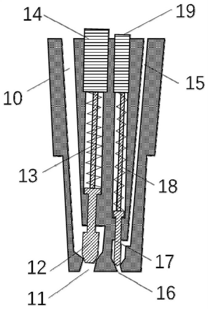
[0032] Such as figure 1 As shown, this embodiment provides a fuel-air integrated injector, including an injector body, on which an air introduction passage 10, a fuel introduction passage 15, an air injection needle valve 12 and a fuel injection needle valve 17 are arranged; The bottom of the injector body is provided with an air injection hole 11 and a fuel injection hole 16; the air injection hole 11 communicates with the air introduction channel 10, and the fuel injection hole 16 communicates with the fuel introduction channel 15; The air injection needle valve 12 is used to control the connection between the air injection hole 11 and the air introduction passage 10, and the fuel injection needle valve 17 is used to control the connection between the fuel injection hole 16 and the fuel introduction channel 10. On and off between channels 15.

[0033] An air injection solenoid valve 14 is arranged on the top of the air injection needle valve 12 , and an air injection needle...

Embodiment 2

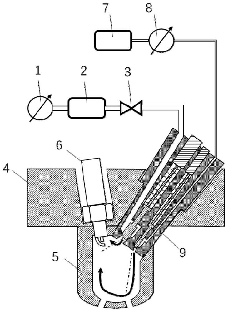
[0037] Such as figure 2 As shown, this embodiment provides an ignition chamber system including the fuel-air integrated injector in Embodiment 1, including a cylinder head or ignition chamber adapter unit 4 and an ignition chamber main body 5; the cylinder head or ignition chamber adapter unit The spark plug 6 and the fuel air integrated injector 9 are arranged on the body 4; the ignition chamber main body 5 is arranged at the bottom of the cylinder head or the ignition chamber adapter unit 4, and the spark plug 6 and the fuel air integrated injector The bottom ends of 9 all extend into the ignition chamber main body 5; the lower part of the ignition chamber main body 5 is an arc structure; the top of the air introduction passage 10 communicates with the air supply branch, and the top of the fuel introduction passage 15 connects with the fuel branch. The roads are connected.

[0038] The air injection hole 11 faces the spark plug 6 , and the fuel injection hole 16 faces obli...

Embodiment 3

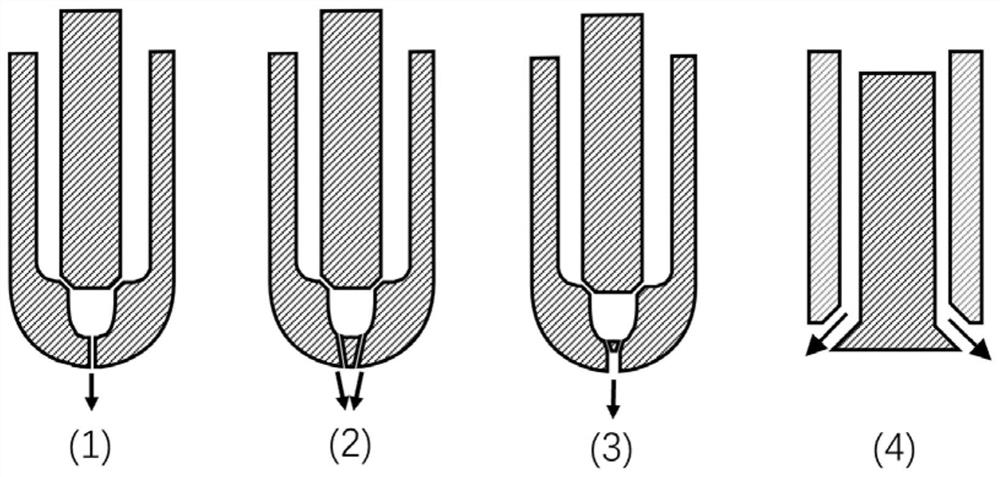
[0047] Such as Figure 4 As shown, this embodiment provides another ignition chamber system including the fuel-air integrated injector in Embodiment 1, including a cylinder head or ignition chamber adapter unit 4 and an ignition chamber main body 5; the cylinder head or ignition chamber adapter A spark plug 6 and a fuel-air integrated injector 9 are arranged on the unit 4; the ignition chamber body 5 is arranged at the bottom of the cylinder head or ignition chamber adapter unit 4, and the spark plug 6 and the fuel-air integrated injection The bottom ends of the device 9 all extend into the ignition chamber main body 5; the lower part of the ignition chamber main body 5 is an arc-shaped structure; the top of the air introduction channel 10 communicates with the air supply branch, and the top of the fuel introduction channel 15 communicates with the fuel Branches are connected.

[0048] The fuel inlet channel 15 of the fuel air integrated injector is close to the side of the s...


PUM


Abstract

The invention discloses a fuel and air integrated ejector and an ignition chamber system comprising the same, and relates to the technical field of combustion of internal combustion engines. An ignition chamber main body is located on an ignition chamber adapter or a cylinder cover. The upper end of the ignition chamber main body is provided with a spark plug and the fuel and air integrated ejector. The lower end of the ignition chamber main body is provided with a small hole connected with a main combustion chamber. An air injection unit and a fuel injection unit are arranged in the fuel and air integrated ejector. The orientations and molded lines of fuel spraying holes and air spraying holes are specially designed to promote fuel gasification and tumble flow respectively, so that combustible gas distribution around the spark plug is guaranteed, and the scavenging efficiency of an ignition chamber is improved. Air supply and fuel supply of the ignition chamber are separated on the basis of the fuel and air integrated ejector, active scavenging of the ignition chamber is achieved, the air amount and the fuel amount are accurately controlled according to different working conditions, and high ignition probability and stable combustion are achieved through accurate control over the equivalence ratio of the ignition chamber. The integrated ejector is compact in structure and suitable for an ignition chamber type internal combustion engine system with a small cylinder diameter.

Description

technical field [0001] The invention relates to the technical field of internal combustion engine combustion, in particular to a fuel-air integrated injector and an ignition chamber system containing it. Background technique [0002] With the gradual strengthening of regulations and policies for energy saving and emission reduction, internal combustion engines for vehicle and ship power and power generation will adopt more lean premixed combustion technology. Mixed gas can improve the controllability and stability of lean premixed combustion. Secondly, the ignition chamber structure used in the high-pressure internal combustion engine can effectively increase the combustion rate, and has obvious effects on avoiding knocking and improving the constant volume of combustion. [0003] Most of the ignition chamber is passive scavenging, that is, the intake air flow of the main combustion chamber enters through the small hole at the lower end of the main body of the ignition cham...

Claims


Application Information

Patent Timeline
IPC IPC(8): F02M57/04F02M61/10F02M61/14F02F1/24F02B23/10
CPCF02M57/04F02M61/10F02M61/14F02F1/242F02B23/10F02B2023/103F02B2023/106Y02T10/12
Inventor 朱晶宇隆武强田华
Owner DALIAN UNIV OF TECH
Why Eureka
Try Eureka