
Machining method of injector partition plate cavity

A processing method and injector technology, applied in jet propulsion devices, machines/engines, rocket engine devices, etc., can solve problems such as low yield, inability to process, and difficult processing

Active Publication Date: 2021-09-10
XIAN YUANHANG VACUUM BRAZING TECH
View PDF7 Cites 1 Cited by
  • Summary
  • Abstract
  • Description
  • Claims
  • Application Information

AI Technical Summary

Problems solved by technology

[0007] The invention provides a method for processing the partition cavity of the injector, which solves the problems that the existing processing method cannot process the partition cavity of the injector, the processing is difficult, and the yield rate is low

Method used


Image

  • Machining method of injector partition plate cavity
  • Machining method of injector partition plate cavity
  • Machining method of injector partition plate cavity

Examples


Embodiment Construction

[0065] The present invention will be described in detail below in combination with specific embodiments.

[0066] A method for processing an injector partition cavity, comprising the following steps:

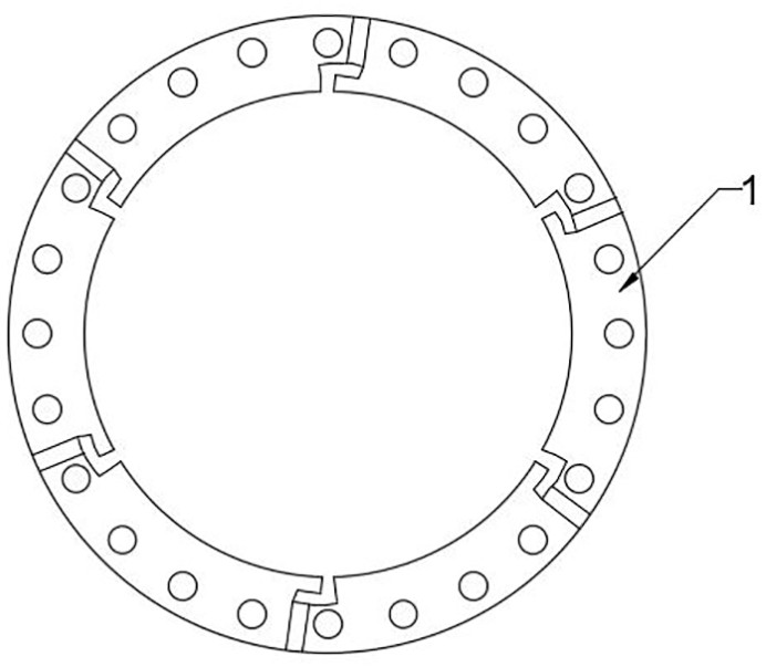
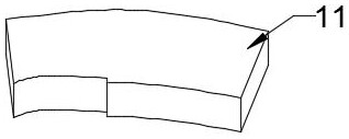
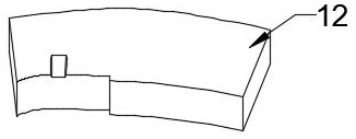
[0067] A1. If figure 1 As shown, the annular body 1 is roughly machined with 06Cr19Ni10 material, a number of reference holes are evenly rough drilled on the annular surface, and six water inlet holes are uniformly bored and milled around its circumference; 1 Cut out six fan-shaped grooves and six wedge-shaped vertical grooves on the inner circumference, and process them to form a stop at the notch; use 06Cr19Ni10 material to process and match the fan-shaped grooves, such as figure 2 The six upper cover plates 11 shown and as image 3 The six lower cover plates 12 shown are processed with 06Cr19Ni10 material to match the wedge-shaped vertical groove as Figure 4 The six wedge-shaped inserts 13 are shown; interfaces matching the six wedge-shaped inserts 13 are processed on th...


PUM


Abstract

The invention relates to the field of spacecraft machining, and discloses a machining method of an injector partition plate cavity. The machining method of the injector partition plate cavity comprises the following steps that A1, a fan-shaped groove and a wedge-shaped vertical groove are cutted on the inner circumference of an annular body; an upper cover plate, a lower cover plate and a wedge-shaped insert are machined, the upper cover plate and the lower cover plate is assembled at the fan-shaped groove, finish machining is carried out on the wedge-shaped insert, the wedge-shaped insert is assembled at a vertical groove, and vacuum brazing is carried out to obtain a partition plate cavity body assembly: A2, a ring groove piece is assembled at the inner circumference of the partition plate cavity body assembly, and fixing and brazing are achieved; wire cutting, assembling and brazing are performed on a hollow plate and a corrugated plate to obtain a partition plate; an adapter is wire cutted and assembled with the partition plate to obtain a honeycomb assembly: A3, the upper end of the wedge-shaped insert and the upper end of the annular groove piece are milled to form a sinking table surface, and a compensation block is finish-milled; a square groove is milled in the middle of a reinforcing plate, and brazing filler metal grooves are milled in the two sides of the square groove and the outer end face of the reinforcing plate; the partition plate cavity body assembly, the reinforcing plate, the honeycomb assembly and the compensation block are assembled, fixed and brazed; and finish machining is carried out after discharging, and argon arc welding is carried out on a water connector at a water inlet hole to obtain an injector partition plate cavity.

Description

technical field [0001] The invention relates to the technical field of aerospace device processing, in particular to a processing method for an injector diaphragm cavity. Background technique [0002] The partition injector is composed of three parts: oil chamber assembly, water chamber assembly and partition chamber assembly. The chambers are positioned by pins and sealed by copper pads, and the injector is assembled and connected with the combustion chamber by bolts; The clapboard cavity is mainly composed of annular body, ring groove, hollow plate, corrugated plate, adapter, water joint and other parts; among them, the clapboard cavity body assembly is formed after the annular body is processed, and the hollow plate and the corrugated plate are assembled, The diaphragm is formed after brazing, the diaphragm and the adapter are assembled and brazed to form a honeycomb assembly, and the diaphragm cavity body assembly is assembled with the honeycomb assembly and the ring gro...

Claims


Application Information

Patent Timeline
Patent Type & Authority Applications(China)
IPC IPC(8): B23P15/00F02K9/52
CPCB23P15/00F02K9/52
Inventor 王程成刘洋康路路周伟超李俊锋
Owner XIAN YUANHANG VACUUM BRAZING TECH
Learn More