Electromagnetic modulator based on plasma metamaterial and multifunctional modulation method

A plasma and modulator technology, applied in the direction of instruments, optics, nonlinear optics, etc., can solve the problem of single frequency range of transparent windows

Active Publication Date: 2021-09-07
NANJING UNIV OF POSTS & TELECOMM
View PDF5 Cites 0 Cited by
  • Summary
  • Abstract
  • Description
  • Claims
  • Application Information

AI Technical Summary

Problems solved by technology

[0007] On the one hand, the present invention aims to solve the technical problem in the prior art that the transparent windows of the electromagnetically induced transparent device based on metamaterials are...

Method used


Image

  • Electromagnetic modulator based on plasma metamaterial and multifunctional modulation method
  • Electromagnetic modulator based on plasma metamaterial and multifunctional modulation method
  • Electromagnetic modulator based on plasma metamaterial and multifunctional modulation method

Examples


Embodiment 1

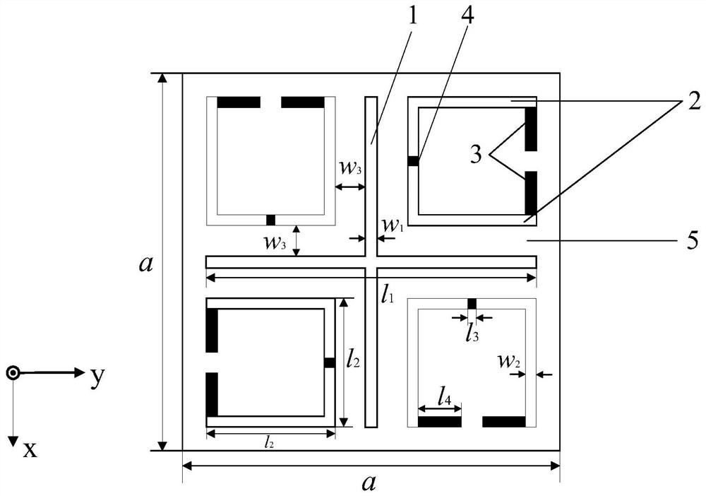
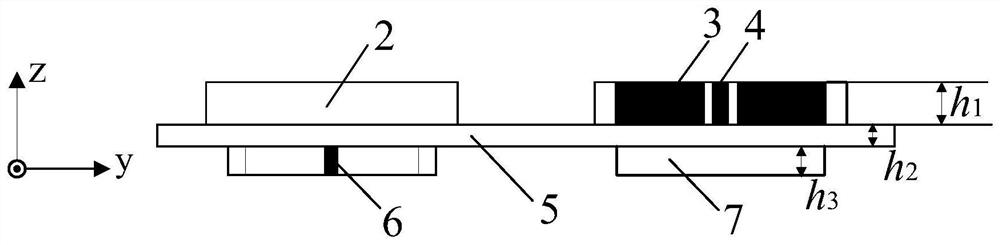
[0034] Embodiment 1: An electromagnetic modulator based on plasmonic metamaterials of the present invention, its structure is as follows Figure 1~Figure 4 As shown, including the substrate (the present embodiment is a polyimide dielectric plate (5)), the upper surface of the polyimide dielectric plate (5) is provided with four rotation-symmetrical points about the center of the polyimide dielectric plate (5). There are four upper-surface split resonant rings, and cross-shaped transverse lines (1) are arranged between the four upper-surface split-shaped resonant rings, and the cross-shaped transverse lines (1) and the split rings are mutually coupled to generate electromagnetically induced transparency.

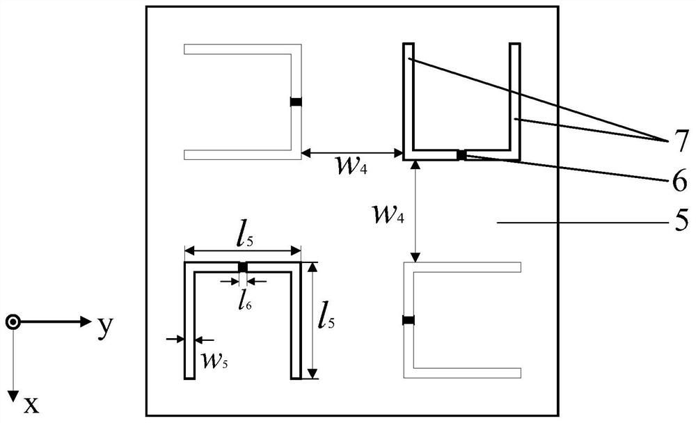
[0035] On the lower surface of the polyimide dielectric plate (5) and the position corresponding to the four upper surface open resonant rings, four lower surface open resonant rings about the 90-degree rotational symmetry of the center are set; the upper surface open resonant...

Embodiment 2

[0042] Embodiment 2. A multifunctional electromagnetic modulation method based on plasmonic metamaterials of the present invention adopts the electromagnetic modulator based on plasmonic metamaterials (such as Figure 1~Figure 4 As shown), when the electromagnetic wave (electric field along the y-axis) is vertically incident, state 1: the electromagnetic modulator exhibits an electromagnetically induced transparency function, controlling the solid-state plasma connection branch (4) of the top split resonator ring and the bottom split resonator ring The solid-state plasma connection branch (6) is excited, and the solid-state plasma extension branch (3) of the top split resonator ring is not excited; State 2: The electromagnetic modulator behaves as an isolator function, controlling the solid-state plasma of the top split resonator ring The extension stub (3) is excited, and the solid plasma connection stub (4) controlling the split resonator ring at the top layer and the solid p...


PUM

PropertyMeasurementUnit
Thicknessaaaaaaaaaa
Thicknessaaaaaaaaaa

Abstract

The invention discloses an electromagnetic modulator based on a plasma metamaterial and a multifunctional modulation method. The upper surface of a substrate is provided with four upper surface opening resonance rings which are in 90-degree rotational symmetry about the center of the substrate, cross-shaped metal crosscutting lines are arranged among the four upper surface opening resonance rings, and four lower surface split resonant rings which are in 90-degree rotational symmetry about the center are arranged at the positions, corresponding to the four upper surface split resonant rings, of the lower surface of the substrate. By controlling excitation states of solid-state plasma resonance branches in different areas, the function of the electromagnetic modulator can be freely switched between electromagnetically-induced transparency and an isolator, two electromagnetically-induced transparent transmission windows both show good slow-wave properties, and meanwhile, the isolator is combined, so that a plurality of frequency points can be converted between a transmission peak and a transmission valley, thereby achieving an on/off modulation effect of electromagnetic wave transmission.

Description

technical field [0001] The invention relates to the field of practical technology and device technology of solid-state plasma and electromagnetic modulators, in particular to electromagnetic modulators and multifunctional modulation methods based on plasma metamaterials. Background technique [0002] Electromagnetic metamaterials, also known as metamaterials, are composite materials that have artificially designed structures and exhibit extraordinary physical properties that are difficult to possess in natural materials according to people's application needs. Because electromagnetic metamaterials have different electromagnetic properties from ordinary materials, they have received considerable attention and applications in the research fields of solid state physics, materials science, optics, and electromagnetism, and are one of the current hot research issues. In recent years, due to its unique electromagnetic properties, metamaterials have derived many potential applicati...

Claims


Application Information

Patent Timeline
IPC IPC(8): G02F1/01G02F1/00G02B1/00
CPCG02F1/0102G02F1/0009G02B1/002
Inventor 章海锋刘国标
Owner NANJING UNIV OF POSTS & TELECOMM
Why Eureka
Try Eureka