An electromagnetic suspension fault-tolerant permanent magnet vernier cylinder motor

A suspension and permanent magnet technology, applied in the direction of magnetic circuits, electromechanical devices, electrical components, etc., can solve the problems of reducing the amount of permanent magnets, reducing motor efficiency, and limiting thrust density, etc., to reduce the amount, save design and processing costs, The effect of reducing thrust pulsation

Inactive Publication Date: 2018-10-09
JIANGSU UNIV
View PDF2 Cites 0 Cited by
  • Summary
  • Abstract
  • Description
  • Claims
  • Application Information

AI Technical Summary

Problems solved by technology

[0004] In addition, for the problem that the overall cost of the long armature structure and the long magnetic pole structure is very high, in order to reduce the cost, the existing method is to use a cylindrical switch flux linkage permanent magnet linear synchronous motor, that is, to place the permanent magnet on the stator or mover On the armature, because the length of the armature is not long, the amount of permanent magnets will be greatly reduced, and the cost will be greatly reduced
But it also brings new problems: on the one hand, the coil surrounds the permanent magnet inside the armature, the heat dissipation condition is too poor, and the temperature rise of the motor is serious; on the other hand, the slot area and the position of the permanent magnet are mutually restricted, and the thrust density is severely limited. reduce motor efficiency

Method used


Image

  • An electromagnetic suspension fault-tolerant permanent magnet vernier cylinder motor
  • An electromagnetic suspension fault-tolerant permanent magnet vernier cylinder motor
  • An electromagnetic suspension fault-tolerant permanent magnet vernier cylinder motor

Examples


Embodiment Construction

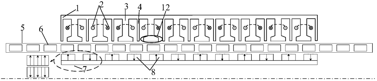
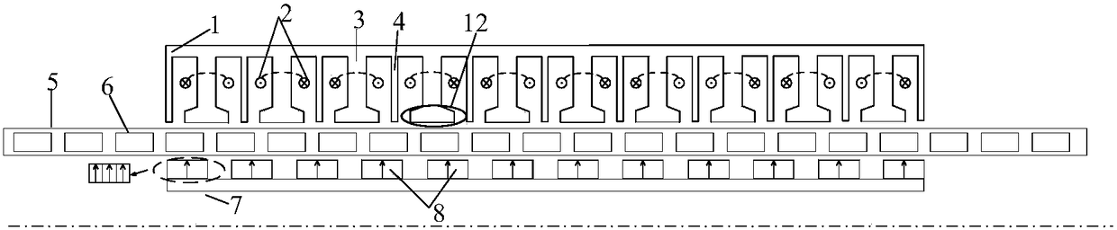
[0026] figure 1 It is an overall schematic diagram of the structure of the electromagnetic suspension fault-tolerant permanent magnet vernier cylinder motor of the present invention.

[0027] Specific embodiments of the present invention will be described in detail below in conjunction with the accompanying drawings

[0028] In order to explain the structural features and beneficial effects of the electromagnetic suspension fault-tolerant permanent magnet vernier cylindrical motor of the present invention more simply and clearly, a detailed description will be made below in conjunction with a specific one.

[0029] In order to illustrate the present invention more clearly, the pole slot ratio of the electromagnetic suspension fault-tolerant permanent magnet vernier cylinder motor of the present invention is embodied, and m=5 is selected, which is a five-phase motor, and the corresponding number of motor slots is n s =2*m*2=20. And the cylindrical motor of this embodiment ado...


PUM


Abstract

The invention discloses an electromagnetic suspension fault-tolerance permanent magnet vernier cylindrical motor, which comprises an inner-side stator, an outer-side stator and a long rotor arranged between the inner-side stator and the outer-side stator. The length of the inner-side stator and the length of the outer-side stator are equal and are smaller than the length of the long rotor. One side of the inner-side stator and one side of the outer-side stator are connected into a whole body through an E-type non-magnetoconductive material pipe; the E-type non-magnetoconductive material pipe is directly and fixedly connected with a carriage; a suspension spring is arranged between the motor long rotor and the E-type non-magnetoconductive material pipe; the other side of the long rotor is directly connected with a vehicle frame and a tyre; and the middle opening direction of the E-type non-magnetoconductive material pipe is the motion direction of the long rotor. The electromagnetic suspension fault-tolerance permanent magnet vernier cylindrical motor realizes mutual separation of an armature and a permanent magnet, can greatly improve space utilization rate of the motor and reduce motor thrust fluctuation, and meanwhile, can reduce use amount of the permanent magnet and the length of the armature; and more importantly, heat dissipation pressure of the motor is reduced, unsprung weight of an electromagnetic suspension system is greatly reduced, and dynamic performance of the electromagnetic suspension system is improved.

Description

technical field [0001] The invention belongs to the technical field of motor design, and more precisely relates to an electromagnetic suspension fault-tolerant permanent magnet vernier cylinder motor, which is especially suitable for automobile suspension systems and other systems requiring high thrust capacity and high reliability. Background technique [0002] With the development of society and the advancement of science and technology, people have higher and higher requirements for ride comfort, safety and stability. As an important part of modern cars, the performance of the suspension system has a great influence on the ride comfort and operation of the car. Stability has an extremely important impact. The research on the performance of the suspension system is highly valued by the industry. As the core component of the active electromagnetic suspension system, the cylinder motor has become the focus of research. [0003] Scholars at home and abroad have proposed many ...

Claims


Application Information

Patent Timeline
Patent Type & Authority Patents(China)
IPC IPC(8): H02K1/17H02K16/04H02K1/16
CPCH02K1/165H02K1/17H02K16/04
Inventor 周华伟陆震刘国海赵文祥吉敬华徐亮陈龙
Owner JIANGSU UNIV
Why Eureka
Try Eureka