


Quick Research
Generate reliable direction feasibility study reports for your R&D in just a few steps.

Technical Q&A
Discover and master advanced knowledge NOW. Basics, ideas, possibilities, all at once.

Find Solutions
As an expert in R&D theories, this can generate solutions to your technical problems instantly.

Evaluate Feasibility
Analyze your overall solution with one click, know your potential R&D risks in advance.

Monitor Landscape
Get weekly tech updates, stay abreast of the latest tech innovations and key insights.
Steel pipe bending device and pipe bending process thereof
A pipe bending device and steel pipe technology, which is applied in the direction of feeding device, positioning device, storage device, etc., can solve the problems of increasing costs and increasing the workload of workers
- Summary
- Abstract
- Description
- Claims
- Application Information
AI Technical Summary
Problems solved by technology
Method used
Image


Examples
Embodiment 1
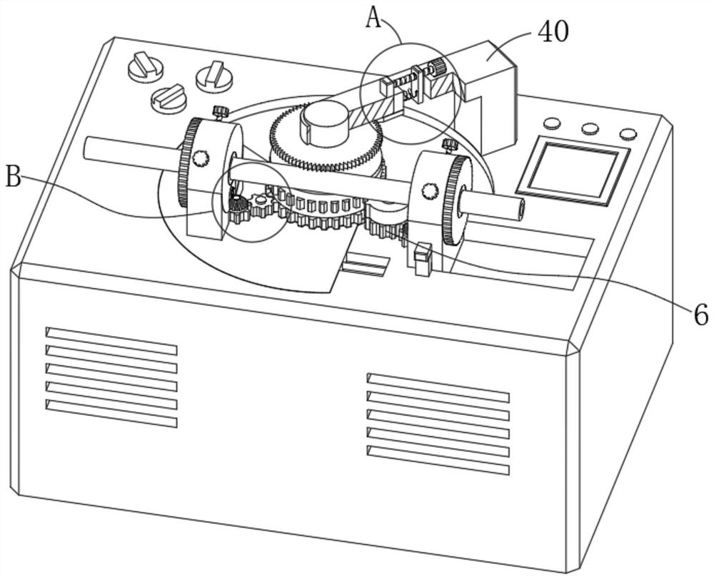
[0031] see Figure 1-2 with Figure 5-10, a steel pipe bending device in the illustration, including a body 1, a jacking mechanism 4, a driving mechanism 5 and a linkage mechanism 6, the body 1 is provided with two bending mechanisms 2, and the two bending mechanisms 2. It is used to fix the two ends of the steel pipe to bend the steel pipe. The two pipe bending mechanisms 2 are equipped with a fixed ring 3. The inner wall of the fixed ring 3 is an anti-slip surface. The jacking mechanism 4 is installed on the body 1. It is used to bend the middle part of the steel pipe to a certain radian in cooperation with the pipe bending mechanism 2. The driving mechanism 5 is installed on the body 1 to drive the pipe bending mechanism 2 to run. The linkage mechanism 6 is installed on the body 1. , used to drive the fixed ring 3 to rotate at a certain angle when the pipe bending mechanism 2 is running.
[0032] The pipe bending mechanism 2 includes a base 7, and the bases 7 on the two p...
Embodiment 2
[0038] see Figure 4-9 Embodiment 2 is described. This embodiment will further illustrate Embodiment 1. The linkage mechanism 6 in the illustration includes a first gear 27 that is rotatably connected to the top surface of the arc block 24 and meshed with the third incomplete gear 22. The top surface of the body 1 is provided with a limit groove 28, which is slidably connected with a base 7 in the limit groove 28. The base 7 is provided with a fixing part 29, and the top surface of the arc block 24 is connected to another base. 7 is fixedly connected, the top surface of the arc block 24 is rotatably connected with a second gear 30 meshing with the first gear 27, and the top end of the second gear 30 is coaxially fixedly connected with a first bevel gear 13. Engaged second bevel gear 31, the top surface of the body 1 is rotatably connected with a third gear 32 meshing with the third incomplete gear 22, and the top surface of the third gear 32 is coaxially fixedly connected with...
Embodiment 3
[0042] see Figure 2-3 with Figure 9 Embodiment 3 is described. This embodiment further describes Embodiment 1. The jacking mechanism 4 in the illustration includes a bracket 40 fixedly installed on the top surface of the body 1. A bending disc 41 is rotatably connected to the bracket 40. The bottom surface of the curved disc 41 is fixedly connected with a gear column 42 which is rotationally connected with the third incomplete gear 22. The gear column 42 is meshed with the fourth incomplete gear 33. The curved disc 41 is provided with a tooth groove 43, so A device slot 44 is provided on the bracket 40, and a limiting block 45 is slidably connected to the slot 43 in the device slot 44, and a third spring 46 is fixedly connected to the limiting block 45. Three springs 46 are fixedly connected with a second slider 47 that is slidably connected with the device groove 44, and the support 40 is rotatably connected with a second screw rod 48, and the second screw rod 48 is thread...
PUM
 Abstract
Description
Claims
Application Information
 - R&D Engineer
- R&D Manager
- IP Professional
- Industry Leading Data Capabilities
- Powerful AI technology
- Patent DNA Extraction
Browse by: Latest US Patents, China's latest patents, Technical Efficacy Thesaurus, Application Domain, Technology Topic, Popular Technical Reports.
© 2024 PatSnap. All rights reserved.Legal|Privacy policy|Modern Slavery Act Transparency Statement|Sitemap|About US| Contact US: help@patsnap.com