
Novel optical fiber conduction luminous floor tile

An optical fiber and a new type of technology, applied in the field of new optical fiber conduction and luminous floor tiles, can solve the problems of damage to the internal circuit, water leakage, water vapor entering, etc., to avoid the problem of water ingress and the effect of super large transmission capacity

Inactive Publication Date: 2021-09-03
范广武
View PDF6 Cites 0 Cited by
  • Summary
  • Abstract
  • Description
  • Claims
  • Application Information

AI Technical Summary

Problems solved by technology

[0005]Because floor tiles are generally used in outdoor places, the working environment is harsh, high temperature, high heat and high humidity directly affect the performance of floor tiles, because they are buried under the ground, rainwater and water Changes in ambient temperature can easily cause moisture to enter, thereby damaging components and products. When the floor tiles are applied on the road, they are always crushed by large-tonnage vehicles, resulting in product deformation and damage to the internal components of the floor tiles. Water leakage due to product deformation and damage to internal circuits

Method used


Image

  • Novel optical fiber conduction luminous floor tile
  • Novel optical fiber conduction luminous floor tile
  • Novel optical fiber conduction luminous floor tile

Examples


Embodiment 1

[0023] Embodiment 1: A new type of optical fiber conduction luminescent floor tile, including a steel structure frame 1, a socket 101 is embedded in the side of the steel structure frame 1, and a protective component that can protect against moisture is provided on the inside of the steel structure frame 1;

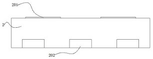
[0024] Wherein: the steel structure outer frame 1 is set in a concave shape, and the steel structure outer frame 1 can provide support and protection for the outer side of the protection component;

[0025] The protection component includes the blind passage protrusion 2, the deceleration protrusion 201, the super pressure-resistant uniform light material 202, the astigmatism lens 3, the output optical fiber 301, the optical fiber splitter 302, the main optical fiber 303 and the optical fiber light source 4, and the blind passage protrusion 2 is embedded outside the steel structure On the inner side of the frame 1, the deceleration protrusion 201 and the super-strong press...


PUM


Abstract

The invention provides a novel optical fiber conduction luminous floor tile which comprises a steel structure outer frame, a socket is embedded in the side face of the steel structure outer frame, and a protection assembly capable of preventing damp is arranged on the inner side of the steel structure outer frame; the protection assembly comprises blind sidewalk protrusions, speed reduction protrusions, a super-strong pressure-resistant dodging material, a diverging lens, an output optical fiber, an optical fiber splitter, a main optical fiber and an optical fiber light source device, the output optical fiber provides electric energy for the optical fiber light source device, the optical fiber light source device converts the electric energy into strong light, and the strong light is inputted into the optical fiber splitter through the main optical fiber; the optical fiber splitter distributes the strong light of the main optical fiber to the output optical fiber, the output optical fiber inputs the light into the astigmatism lens, and then the light passes through the super-strong pressure-resistant dodging material so that the whole floor tile emits light, and the light attenuation of the current optical fiber is little, the service life is longer and is dozens of times of that of a cable, and the cost of the cable is 20 times of that of the optical fiber, and the optical fiber has ultra-large transmission capacity and is free of so-called electromagnetic interference.

Description

technical field [0001] The invention relates to the technical field of floor tiles, in particular to a novel optical fiber conductive luminous floor tile. Background technique [0002] Traditional deceleration floor tiles and tactile floor tiles do not have the ability to emit light due to no energy supplement. Only when vehicles are driving on them, there will be strong vibrations, or people will feel unevenness on the soles of their feet when walking on them. There is no visibility and no advance Early warning function, low safety warning effect; [0003] Aiming at the technical problems of the floor tiles mentioned above, after searching, it is found that there is a patent number CN201910355181.2 for a luminous floor tile, which can protect the floor tile module, improve installation efficiency, and improve the embedment of the floor tile module. Subsequent stability and electrical safety; [0004] Based on the application of ground roads, people have invented luminous ...

Claims


Application Information

Patent Timeline
Patent Type & Authority Applications(China)
IPC IPC(8): E01C15/00E01C17/00F21V5/04F21V8/00F21V33/00F21Y115/10
CPCE01C15/00E01C17/00F21V5/04F21V33/006E01C2201/08F21V2200/10F21Y2115/10
Inventor 范广武
Owner 范广武
Learn More