Wearable unmanned aerial vehicle

A technology of unmanned aerial vehicles and wings, applied in the field of unmanned aerial vehicles, can solve the problems of poor applicability, single function, and difficulty in fully reflecting the role of civil unmanned aerial vehicles.

Inactive Publication Date: 2021-09-03
NINGBO UNIV
View PDF6 Cites 3 Cited by
  • Summary
  • Abstract
  • Description
  • Claims
  • Application Information

AI Technical Summary

Problems solved by technology

[0003] However, the existing civilian drones are large in size, single in function, and poor in applicability, and it is difficult to fully reflect the role of civilian drones

Method used


Image

  • Wearable unmanned aerial vehicle
  • Wearable unmanned aerial vehicle
  • Wearable unmanned aerial vehicle

Examples


Embodiment 1

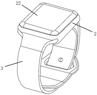
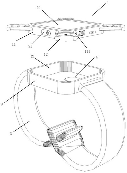
[0028] Embodiment one: if Figure 1-4 As shown, a wearable drone includes a drone body 1, a base 2 and a wristband 3. The base 2 is embedded with an electromagnet assembly 4 capable of switching magnetic poles. The groove 21 accommodated by the drone body 1, the two ends of the wristband 3 are fixedly connected to the two opposite side walls of the base 2, and the drone body 1 is provided with a camera 51 that attracts or repels each other with the electromagnet assembly 4. magnet (not shown in the figure), GPS locator 53, touch display screen 54, antenna 55, speaker 56, microphone 57, laser radar 58, illumination source 59, processor 61 and first built-in power supply 62, camera device 51, GPS locator 53, touch display screen 54, antenna 55, loudspeaker 56, microphone 57, laser radar 58, illumination source 59 are electrically connected with processor 61 respectively, the output end of the first built-in power supply 62 and the power input end of processor 61 Electrically co...

Embodiment 2

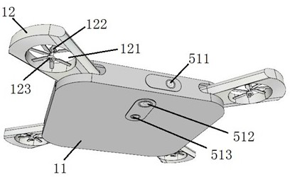
[0030] Embodiment 2: the remaining parts are the same as Embodiment 1, the difference is that the UAV body 1 includes a fuselage 11 and n wings 12, and the side wall of the fuselage 11 is provided with n storage slots 111, where n is An integer greater than or equal to 2, n wings 12 correspond to n storage slots 111 one-to-one, and a drive unit (not shown in the figure) is arranged in the storage slot 111, and the drive unit is used to control the wing 12 to stretch out the corresponding storage The slot 111 can be stored in the corresponding storage slot 111, and the wing 12 can be stored by setting the storage slot 111 to make the structure more compact and easy to carry.

[0031] In this embodiment, the wing 12 is provided with a vertical through hole 121, and the through hole 121 is provided with a propeller 122 and a driving motor 123 for controlling the rotation of the propeller 122. The driving motor 123 is connected to the first built-in power supply through an electron...

Embodiment 3

[0037] Embodiment 3: the rest is the same as Embodiment 2, the difference is that the camera device 51 includes one of a first optical camera 511 for taking pictures, a second optical camera 512 for aerial video recording, and a thermal imaging camera 513 .


PUM


Abstract

The wearable unmanned aerial vehicle comprises an unmanned aerial vehicle body, a base and a wrist strap, an electromagnet assembly capable of switching magnetic poles is embedded in the base, a groove for containing the unmanned aerial vehicle body is formed in the upper end face of the base, and the two ends of the wrist strap are fixedly connected with the two opposite side walls of the base; the unmanned aerial vehicle body is provided with a camera device, a magnet which attracts or repels the electromagnet assembly, a GPS positioner, a touch display screen, an antenna, a loudspeaker, a microphone, a laser radar, an illumination light source, a processor and a first built-in power supply, and the camera device, the GPS positioner, the touch display screen, the antenna, the loudspeaker, the microphone, the laser radar and the illumination light source are electrically connected with the processor. The output end of the first built-in power supply is electrically connected with the power input end of the processor, and the electromagnet assembly and the processor are electrically connected with the control terminal in a wireless mode. The multifunctional pen container has the advantages of integrating multiple functions and being wide in application range.

Description

technical field [0001] The invention belongs to the technical field of drones, in particular to a wearable drone. Background technique [0002] UAV is an unmanned aircraft mainly controlled by wireless remote control or its own program. With the development of science and technology, the application of UAV is becoming more and more extensive, and there are more and more types of UAV. UAVs are mostly used for aerial photography and detection in civilian use. They are not restricted by terrain and other environments. Many outdoor sports enthusiasts like to carry UAVs outdoors for aerial photography. In addition, UAVs can also be used for rescue and disinfection liquid spraying etc. [0003] However, the existing civilian drones are large in size, single in function, and poor in applicability, making it difficult to fully reflect the role of civilian drones. Contents of the invention [0004] The technical problem to be solved by the present invention is to provide a wearab...

Claims


Application Information

Patent Timeline
Patent Type & Authority Applications(China)
IPC IPC(8): B64C39/02B64D47/00
CPCB64C39/024B64C39/026B64C39/028B64D47/00B64U2101/00B64U50/19B64U30/20B64U2201/20B64U80/60B64U10/10
Inventor 夏慧娟王园园
Owner NINGBO UNIV
Why Eureka
Try Eureka