Stainless steel pipe cutting clamp

A technology for stainless steel pipes and fixtures, which is applied in the direction of shearing devices, manufacturing tools, maintenance and safety accessories, etc. It can solve the problems of limited application range, unstable clamping, high temperature, etc., and achieves wide application range and easy recycling. , high automation effect

Inactive Publication Date: 2021-09-03
曹萍
View PDF6 Cites 0 Cited by
  • Summary
  • Abstract
  • Description
  • Claims
  • Application Information

AI Technical Summary

Problems solved by technology

[0005] The purpose of the present invention is to provide a stainless steel pipe cutting jig with stable clamping, wide application range and automatic cooling for the above problems of unstable clamping, limited application range and high temperature during cutting

Method used


Image

  • Stainless steel pipe cutting clamp
  • Stainless steel pipe cutting clamp
  • Stainless steel pipe cutting clamp

Examples


Embodiment

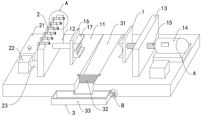
[0028] Such as Figure 1-5 As shown, a stainless steel pipe cutting fixture, including:

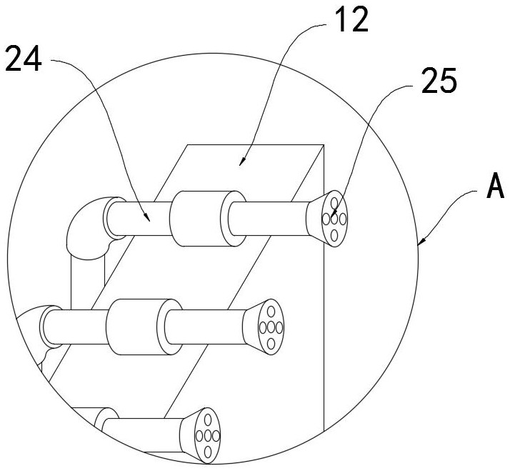
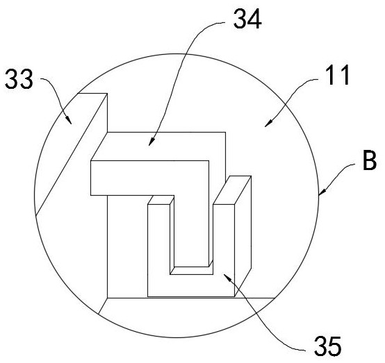
[0029] The clamping mechanism 1 includes a workbench 11, a first baffle 12, a second baffle 13, a cylinder 14, a push rod 15, two mounting plates 16 and two clamping parts 17, the first baffle 12 and the second baffle The plates 13 are vertically and fixedly connected to the upper surface of the workbench 11, one of the mounting plates 16 is fixedly mounted on the side wall of the first baffle plate 12 through a connecting rod, and the other mounting plate 16 is fixedly connected to the push rod 15, and the push rod 15 runs through Slidingly connected in the second baffle plate 13, the cylinder 14 is fixedly installed on the workbench 11. It is worth mentioning that the bottom pad of the cylinder 14 is provided with an air cushion 4, and the steel pipe vibrates during the cutting process, and the vibration is transmitted to the cylinder 14 At the position, the air cushion 4 can play a go...


PUM


Abstract

The invention belongs to the technical field of stainless steel pipe machining, and particularly relates to a stainless steel pipe cutting clamp. The stainless steel pipe cutting clamp comprises a clamping mechanism, wherein the clamping mechanism comprises a workbench, a first baffle, a second baffle, an air cylinder, a push rod, two mounting plates and two clamping pieces, and the first baffle and the second baffle are both perpendicularly and fixedly connected to the upper surface of the workbench; one mounting plate is fixedly arranged on the side wall of the first baffle through a connecting rod, and the other mounting plate is fixedly connected with the push rod; the push rod is slidably connected into the second baffle in a penetrating mode; and the air cylinder is fixedly arranged on the workbench, and the output end of the air cylinder is connected with the push rod and used for driving the push rod to slide. According to the stainless steel pipe cutting clamp, a steel pipe to be cut can be clamped stably, and the stainless steel pipe cutting clamp is suitable for steel pipes with different diameters; and meanwhile, during clamping, water spraying cooling can be conducted on the steel pipe, the problem that a steel pipe body is too hot in the cutting process to cause deformation and scrapping is avoided, and high-temperature flying chips are effectively prevented from flying out to hurt people.

Description

technical field [0001] The invention belongs to the technical field of stainless steel pipe processing, and in particular relates to a stainless steel pipe cutting jig. Background technique [0002] In the daily processing of stainless steel pipes, it is often necessary to cut according to the actual use. Different processing has different cutting requirements and different cutting methods. Commonly used cutting methods for stainless steel pipes include grinding wheel machine cutting, circular saw machine cutting, and fully automatic machine cutting. Cutting and laser cutting, etc., in the cutting process of stainless steel pipes, they need to be clamped and fixed by clamps to ensure the cutting quality. [0003] Most of the clamping mechanisms in the existing stainless steel pipe cutting jigs are fixed in structure and cannot be adjusted according to the diameter of the steel pipe to be cut, which often leads to problems of unstable clamping and easy slippage, and even the ...

Claims


Application Information

Patent Timeline
IPC IPC(8): B23D33/02B23Q11/10
CPCB23D33/02B23Q11/10
Inventor 曹萍
Owner 曹萍
Why Eureka
Try Eureka