Clamping tool for machining Hawking metal surface
A metal surface and clamping technology, which is applied in metal processing equipment, metal processing machinery parts, clamping, etc., can solve the problems that affect the efficiency of processing, easy slipping of parts, cumbersome clamping, etc., to improve efficiency and increase production efficiency effect
- Summary
- Abstract
- Description
- Claims
- Application Information
AI Technical Summary
Problems solved by technology
Method used
Image

Examples
Embodiment 1
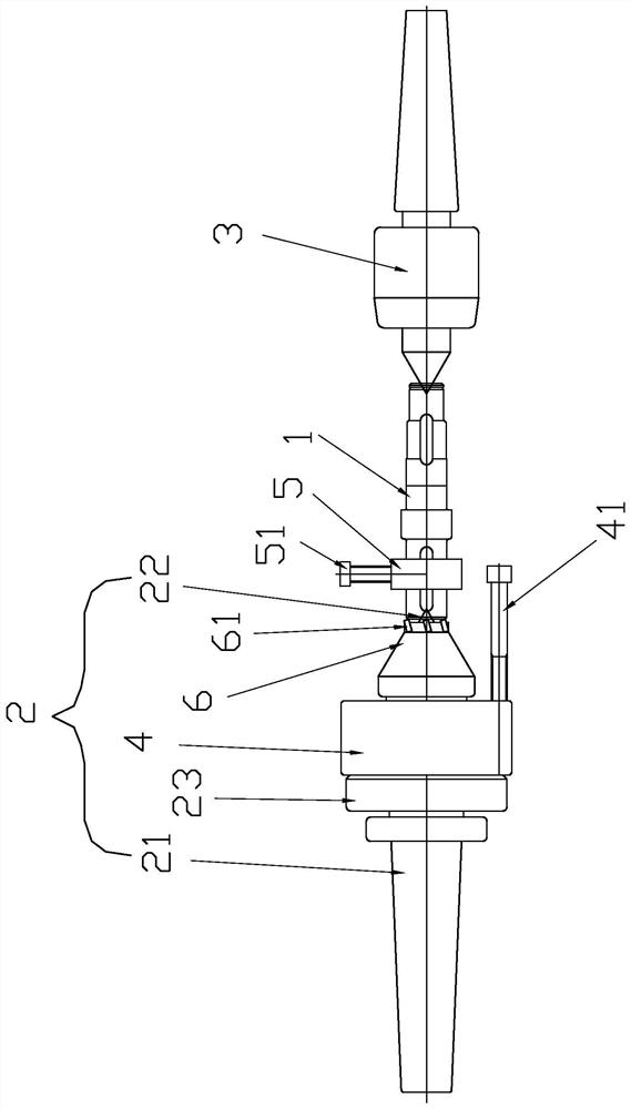
[0025] Such as figure 1 As shown, a Hawker metal surface processing and clamping tool is used to clamp the output shaft 1 with a central hole at both ends, including a hydraulically driven top 2 installed at one end of the main shaft of the lathe, and a The driven top 3, the first shaft sleeve 4 and the second shaft sleeve 5, the hydraulically driven top 2 and the driven top 3 are respectively against the two ends of the output shaft 1, and the hydraulically driven top 1 includes a rotating rod 21, a thimble 22. The sleeve 23 installed on the outer wall of the rotating rod 21 and the clamping mechanism set at the end of the rotating rod 21 corresponding to the thimble 22 for clamping the outer peripheral surface of the output shaft 1, the first sleeve 4 is sleeved on the rotating rod 21 , and fixedly connected with the sleeve 23 through the first fastener 41, the second sleeve 5 is sleeved on the outer peripheral surface of the output shaft 1, and fixedly connected with the ou...
Embodiment 2
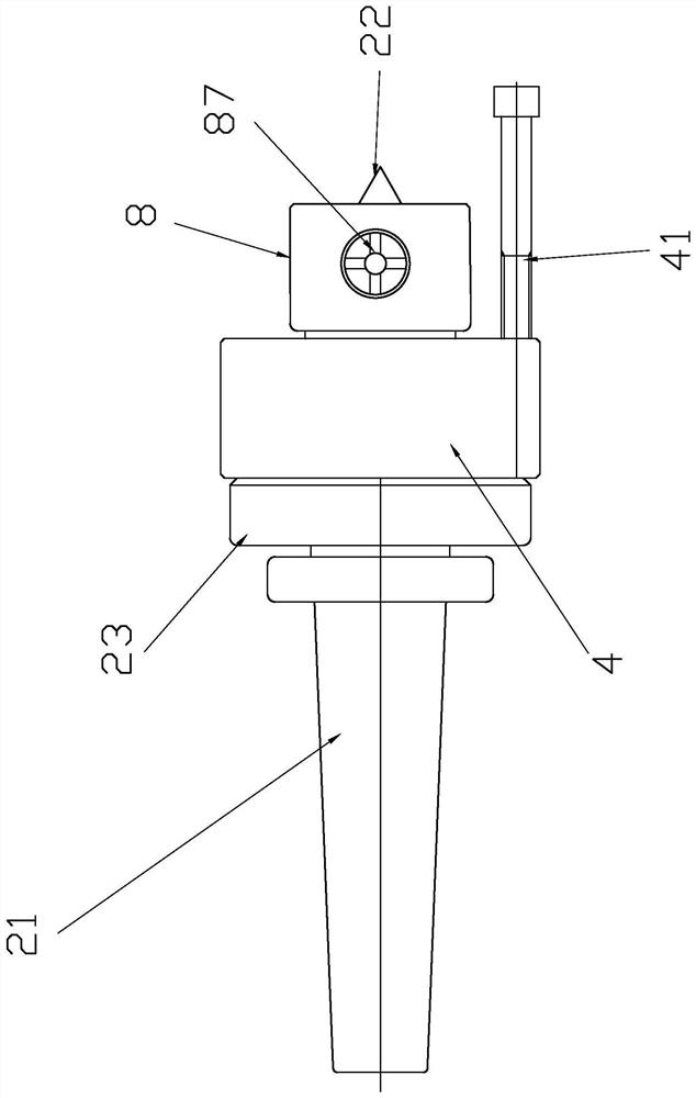
[0027] Such as figure 2As shown, a Hawker metal surface processing and clamping tool is used to clamp the output shaft 1 with a central hole at both ends, including a hydraulically driven top 2 installed at one end of the main shaft of the lathe, and a The driven top 3, the first shaft sleeve 4 and the second shaft sleeve 5, the hydraulically driven top 2 and the driven top 3 are respectively against the two ends of the output shaft 1, and the hydraulically driven top 1 includes a rotating rod 21, a thimble 22. The sleeve 23 installed on the outer wall of the rotating rod 21 and the clamping mechanism set at the end of the rotating rod 21 corresponding to the thimble 22 for clamping the outer peripheral surface of the output shaft 1, the first sleeve 4 is sleeved on the rotating rod 21 , and fixedly connected with the sleeve 23 through the first fastener 41, the second sleeve 5 is sleeved on the outer peripheral surface of the output shaft 1, and fixedly connected with the ou...
Embodiment 3
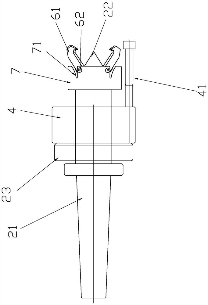
[0029] Such as image 3 , Figure 4 As shown, a Hawker metal surface processing and clamping tool is used to clamp the output shaft 1 with a central hole at both ends, including a hydraulically driven top 2 installed at one end of the main shaft of the lathe, and a The driven top 3, the first shaft sleeve 4 and the second shaft sleeve 5, the hydraulically driven top 2 and the driven top 3 are respectively against the two ends of the output shaft 1, and the hydraulically driven top 1 includes a rotating rod 21, a thimble 22. The sleeve 23 installed on the outer wall of the rotating rod 21 and the clamping mechanism set at the end of the rotating rod 21 corresponding to the thimble 22 for clamping the outer peripheral surface of the output shaft 1, the first sleeve 4 is sleeved on the rotating rod 21 , and fixedly connected with the sleeve 23 through the first fastener 41, the second sleeve 5 is sleeved on the outer peripheral surface of the output shaft 1, and fixedly connecte...
PUM
 Abstract
Description
Claims
Application Information
 - R&D
- Intellectual Property
- Life Sciences
- Materials
- Tech Scout
- Unparalleled Data Quality
- Higher Quality Content
- 60% Fewer Hallucinations
Browse by: Latest US Patents, China's latest patents, Technical Efficacy Thesaurus, Application Domain, Technology Topic, Popular Technical Reports.
© 2025 PatSnap. All rights reserved.Legal|Privacy policy|Modern Slavery Act Transparency Statement|Sitemap|About US| Contact US: help@patsnap.com