
Planar integrated array antenna

An array antenna and plane technology, applied in antennas, antenna arrays, resonant antennas, etc., can solve the problems of unsuitable broadband high-speed communication scenarios, low antenna radiation efficiency, and narrow antenna bandwidth, etc., to facilitate industrial promotion, high gain, and work. Bandwidth effect

Pending Publication Date: 2021-08-31
SENWELLEN (SHENZHEN) COMM TECH CO LTD
View PDF0 Cites 0 Cited by
  • Summary
  • Abstract
  • Description
  • Claims
  • Application Information

AI Technical Summary

Problems solved by technology

[0004] Among all planar antenna arrays, microstrip patch antenna arrays are one of the most common thin antennas in the microwave band, however, due to the low antenna radiation efficiency caused by factors such as high dielectric loss in the millimeter wave band, they are limited Applications in mmWave frequency band
[0005] The slotted waveguide array antenna is another commonly used planar antenna array structure, but the traditional slotted waveguide array antenna has a narrow bandwidth and is not suitable for broadband high-speed communication scenarios

Method used


Image

  • Planar integrated array antenna
  • Planar integrated array antenna
  • Planar integrated array antenna

Examples


Embodiment Construction

[0040] A broadband high-gain planar integrated array antenna proposed by the present invention and its design method are specifically described below through a detailed description of an embodiment. An example of the embodiment is shown in the accompanying drawings, wherein the same reference numerals represent the same meanings throughout. The embodiments described below by referring to the figures are exemplary only for explaining the present invention and should not be construed as limiting the present invention.

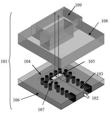
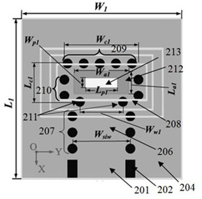
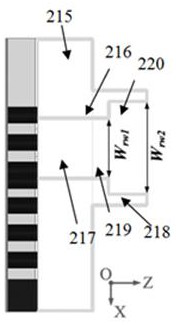
[0041] figure 1 It is a structural diagram of the antenna unit of the present invention. The broadband high-gain antenna unit 101 is composed of upper and lower layers. The lower layer includes the first input port 102, the first layer of dielectric integrated waveguide 103, the first layer of dielectric integrated waveguide cavity 104, the first Layer dielectric integrated waveguide cavity back patch 105, first layer dielectric 106, first signal transition windo...


PUM

PropertyMeasurementUnit
Thicknessaaaaaaaaaa
Lengthaaaaaaaaaa

Abstract

The invention provides a planar integrated array antenna, and the antenna comprises an antenna unit; the antenna unit is composed of a dielectric integrated waveguide cavity back surface patch and a stepped waveguide horn; the dielectric integrated waveguide cavity back surface patch serves as a broadband waveform impedance converter to excite the stepped waveguide horn on the upper layer, and by increasing the radiation aperture, the gain of the antenna unit is enhanced by adopting a stepped waveguide horn, and a 2 * 2 sub-array of which the unit spacing is greater than the wavelength is designed based on the proposed antenna unit. And a groove is etched between the units to serve as an auxiliary radiation source, so that the gain of the 2 * 2 sub-array is improved, and a high sidelobe is inhibited. In order to further improve the gain, a 16 * 16 unit array antenna is designed, manufactured and measured, and the 16 * 16 unit array antenna realizes 22.4% of the impedance bandwidth of -10 dB and the peak gain of 28.8-30.9 dBi within the frequency range of 71-88.5 GHz. By virtue of the advantages of wider working bandwidth, high gain, small and exquisite appearance and low cross polarization, the array antenna disclosed by the invention is suitable for popularization and application in an E-band wireless backhaul system.

Description

technical field [0001] The invention belongs to the communication field, and in particular relates to a broadband high-gain planar integrated array antenna structure. Background technique [0002] With the development of 5G technology, mobile data applications and traffic are increasing exponentially, and millimeter wave technology has broad prospects for broadband communication applications in 5G wireless networks. Such applications usually require millimeter wave antennas with high gain, broadband and low crossover polarization. [0003] By using conventional lens and reflector antennas, it is easy to achieve high-gain antennas with high directivity, small size, light weight and easier installation. Such antennas are generally more attractive for long-distance mmWave wireless communication applications. [0004] Among all planar antenna arrays, microstrip patch antenna arrays are one of the most common thin antennas in the microwave band, however, due to the low antenna ...

Claims


Application Information

Patent Timeline
IPC IPC(8): H01Q21/00H01Q13/02H01Q1/50H01Q9/04
CPCH01Q1/50H01Q9/0414H01Q13/02H01Q21/00
Inventor 蒋溱陈国胜姚魁李瑞兵
Owner SENWELLEN (SHENZHEN) COMM TECH CO LTD
Learn More