
On-chip magnetic core power inductor with inductance value changing along with working current

A technology of working current and power inductance, applied in the application of transformer/inductor core, transformer/inductor shell, magnetic film to substrate, etc., can solve the problem of not being able to maintain low ripple current transient response capability, etc. question

Pending Publication Date: 2021-08-31
UNIV OF ELECTRONICS SCI & TECH OF CHINA
View PDF11 Cites 0 Cited by
  • Summary
  • Abstract
  • Description
  • Claims
  • Application Information

AI Technical Summary

Problems solved by technology

[0005] The purpose of the present invention is to provide an on-chip magnetic core power inductor whose inductance value changes with the working current to solve the problem that the switching power supply in the background technology cannot maintain low ripple current and good transient response capability at the same time, so that the inductance is It has a small inductance value at low current and a large inductance value at high current; based on the on-chip magnetic core power inductor proposed by the present invention, it can effectively improve the transient response capability of the power supply, reduce the ripple current at the same time, and improve power stability

Method used


Image

  • On-chip magnetic core power inductor with inductance value changing along with working current
  • On-chip magnetic core power inductor with inductance value changing along with working current
  • On-chip magnetic core power inductor with inductance value changing along with working current

Examples


Embodiment

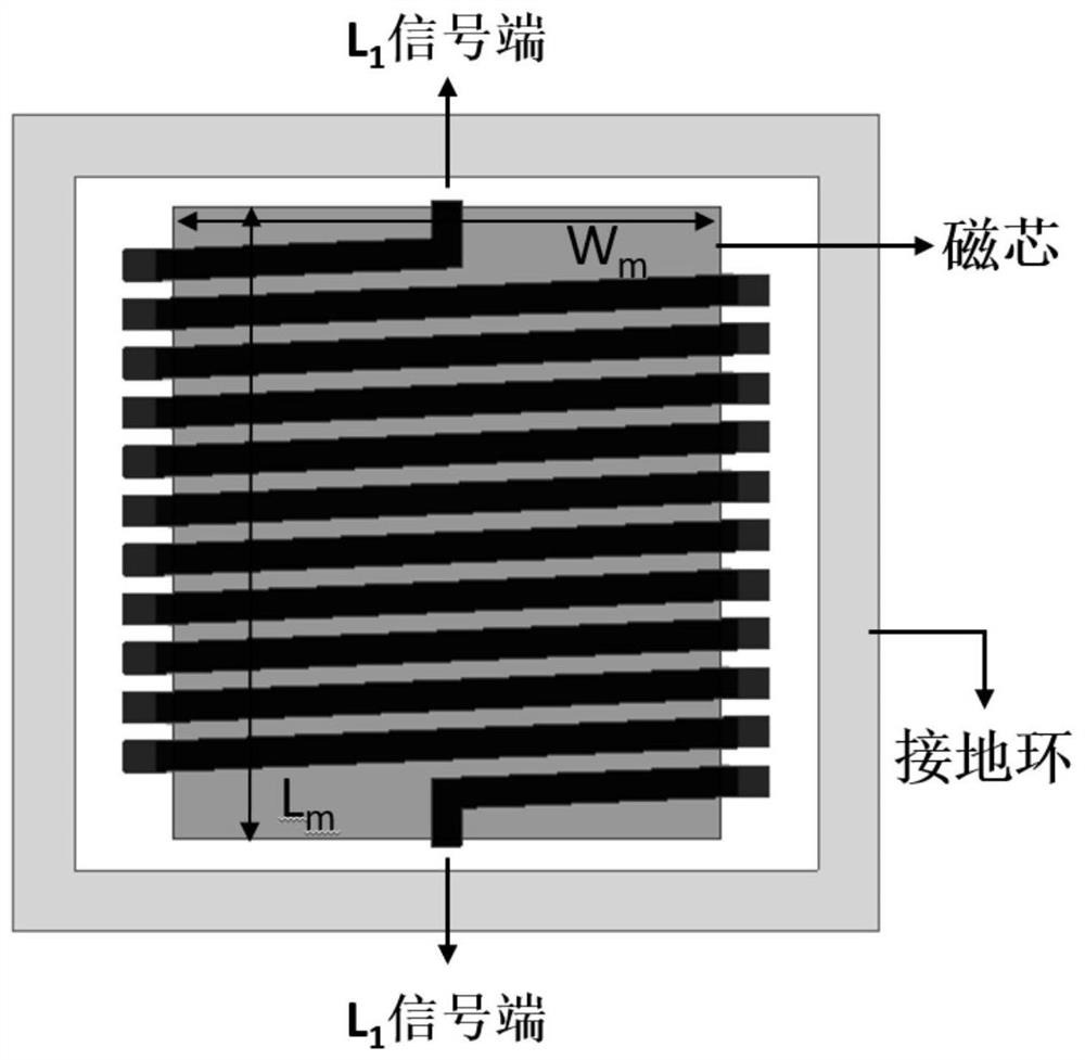
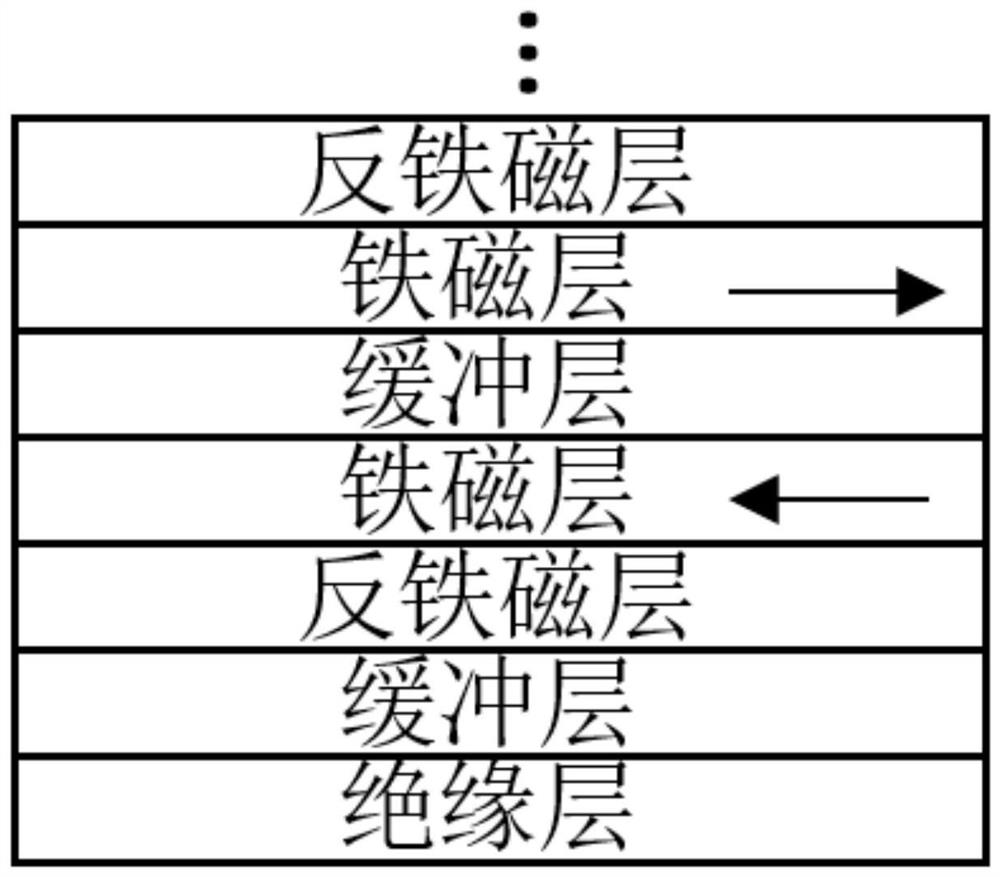
[0027] The on-chip magnetic core power inductor whose inductance value changes with the working current provided in this embodiment is prepared on a silicon chip by MEMS technology; the winding is made of metallic copper material with a thickness T c 12μm, width w c is 25μm, the coil gap g is 15μm; the width of the anisotropic magnetic core film W m =445μm, length L m =575 μm; the magnetic core film adopts [insulating layer / buffer layer / antiferromagnetic layer (AF) / ferromagnetic layer (FM) / buffer layer / ferromagnetic layer (FM) / antiferromagnetic layer (AF)] n Multi-layer film structure; insulating layer is SiO 2 The thin film is prepared by DC magnetron sputtering method: the sputtering power is 100-200W, the sputtering pressure is 0.2-0.7Pa, and the deposition time is controlled so that SiO 2 The thickness of the film is 4-10nm; the buffer layer is Cu metal thin film, which is prepared by DC magnetron sputtering method: the sputtering power is 25-60W, the sputtering pressur...


PUM

PropertyMeasurementUnit
thicknessaaaaaaaaaa
thicknessaaaaaaaaaa
thicknessaaaaaaaaaa

Abstract

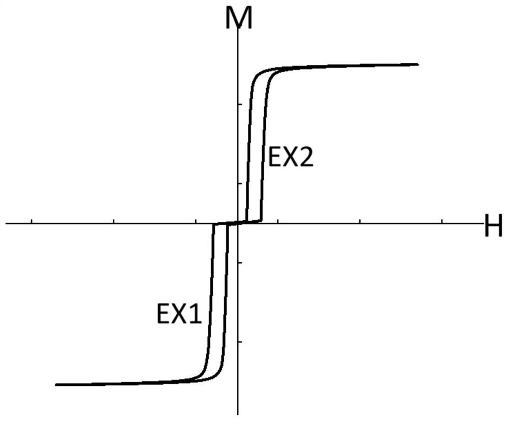
The invention belongs to the technical field of passive integrated devices, and particularly provides an on-chip magnetic core power inductor with an inductance value changing along with working current. The inductor is applied to a switching power supply to solve the problem that the switching power supply cannot keep low ripple current and good transient response capability at the same time, and does not need additional components or control circuits. In the invention, an anisotropic magnetic core film adopts an [insulating layer / lower buffer layer / lower antiferromagnetic layer / lower ferromagnetic layer / upper buffer layer / upper ferromagnetic layer / upper antiferromagnetic layer]n multi-layer film structure, and the magnetic core film has lower magnetic conductivity in a low field and higher magnetic conductivity in a high field by utilizing the effect of an anti-parallel exchange bias field between layers of the magnetic core film; when the direct current bias of the inductor is relatively high, the inductor has a relatively large inductance value, so that the ripple current is reduced; and when the power supply is in a turn-on (turn-off) state, the current value on the inductor is relatively small, the inductance value is relatively low, and the transient response capability is improved.

Description

technical field [0001] The invention belongs to the technical field of passive integrated devices, and in particular relates to an on-chip magnetic core power inductor whose inductance value changes with the working current. Background technique [0002] As the architecture of the central processing unit (CPU) and graphics processing unit (GPU) continues to develop towards multi-core, the power consumption density of the chip continues to increase; in order to reduce the power consumption of the chip, an on-chip power supply with dynamic voltage frequency scaling (DVFS) capability must be used The system provides fast response and accurate power supply to the chip; however, in a switching power supply, too small a filter inductance will increase the ripple current and reduce the accuracy of the output voltage, and an excessively large inductance will reduce the transient response capability of the power supply. [0003] For the above-mentioned problem that switching power su...

Claims


Application Information

Patent Timeline
Patent Type & Authority Applications(China)
IPC IPC(8): H01F27/24H01F27/02H01F41/14
CPCH01F27/24H01F27/02H01F41/14
Inventor 白飞明张治硼何禹含张怀武
Owner UNIV OF ELECTRONICS SCI & TECH OF CHINA
Learn More