


Quick Research
Generate reliable direction feasibility study reports for your R&D in just a few steps.

Technical Q&A
Discover and master advanced knowledge NOW. Basics, ideas, possibilities, all at once.

Find Solutions
As an expert in R&D theories, this can generate solutions to your technical problems instantly.

Evaluate Feasibility
Analyze your overall solution with one click, know your potential R&D risks in advance.

Monitor Landscape
Get weekly tech updates, stay abreast of the latest tech innovations and key insights.
Milling chatter prediction method for thin bottom plate
A technology of milling chatter and prediction method, applied in special data processing applications, instruments, electrical digital data processing, etc., can solve the problem of reduced accuracy in the stability domain, no consideration of the influence of dynamic cutting forces, and unfavorable machining process stability parameters selection and other problems, to achieve the effect of improving the accuracy of stability prediction
- Summary
- Abstract
- Description
- Claims
- Application Information
AI Technical Summary
Problems solved by technology
Method used
Image


Examples
Embodiment 1
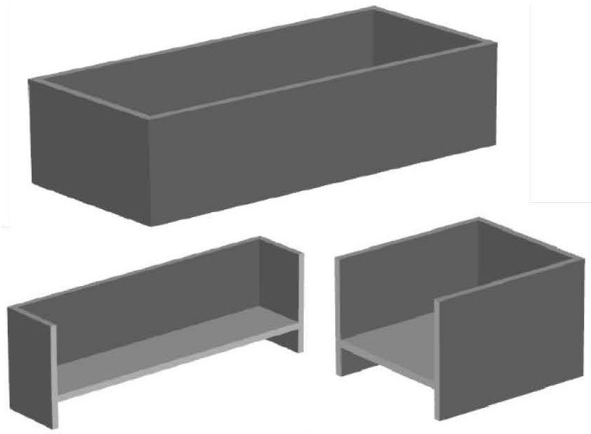
[0045] Example 1: The size of the cutting part of the cavity is 172mm×70mm×3mm, the material is aluminum alloy 7075, the modulus of elasticity is 71.0GPa, and the density is 2830kg / m 3 , Poisson's ratio is 0.3.
[0046] 1. The dynamic state equation of the workpiece during milling is:
[0047]
[0048] m W ,C W ,KW Represents the mass, damping, and stiffness matrices of the initial workpiece; and Q W (t) represents the acceleration, velocity and displacement vector of the workpiece under physical coordinates; F W (t) represents the dynamic cutting force acting on the workpiece.
[0049] 2. During the milling process of thin base plate, the dynamic cutting force acting on the workpiece at time t:
[0050]
[0051] K tra Represents the cutting force coefficient matrix, K tra =[875,350,296] T ; g(φ j (t,a p )) represents the cutting state function, its value is 1 when the tooth participates in cutting, and the value is 0 when it does not participate in cutting; ...
Embodiment 2
[0073] Example 2: The size of the processed part of the cavity is 180mm×65mm×3.5mm; the material is aluminum alloy 7050, the modulus of elasticity is 71.7GPa, and the density is 2830kg / m 3 , Poisson's ratio is 0.3.
[0074] 1. The dynamic state equation of the workpiece during milling is:
[0075]
[0076] m W ,C W ,K W Represents the mass, damping, and stiffness matrices of the initial workpiece; and Q W (t) represents the acceleration, velocity and displacement vector of the workpiece under physical coordinates; F W (t) represents the dynamic cutting force acting on the workpiece.
[0077] 2. During the milling process of thin base plate, the dynamic cutting force acting on the workpiece at time t:
[0078]
[0079] K tra Represents the cutting force coefficient matrix, K tra =[896,371,311] T ; g(φ j (t,a p )) represents the cutting state function, its value is 1 when the tooth participates in cutting, and the value is 0 when it does not participate in cut...
PUM
| Property | Measurement | Unit |
|---|---|---|
| Elastic modulus | aaaaa | aaaaa |
| Density | aaaaa | aaaaa |
| Elastic modulus | aaaaa | aaaaa |
Abstract
Description
Claims
Application Information
 - R&D Engineer
- R&D Manager
- IP Professional
- Industry Leading Data Capabilities
- Powerful AI technology
- Patent DNA Extraction
Browse by: Latest US Patents, China's latest patents, Technical Efficacy Thesaurus, Application Domain, Technology Topic, Popular Technical Reports.
© 2024 PatSnap. All rights reserved.Legal|Privacy policy|Modern Slavery Act Transparency Statement|Sitemap|About US| Contact US: help@patsnap.com