
A sample storage device for ecological environment monitoring

A technology for environmental monitoring and storage devices, applied in unloading devices, packaging of fragile items, packaging, etc., can solve problems such as easy adhesion of sediment, sediment on the surface of test tubes staying in the fixed groove, and difficult to put in test tubes.

Active Publication Date: 2022-06-21
河北省廊坊生态环境监测中心
View PDF7 Cites 0 Cited by
  • Summary
  • Abstract
  • Description
  • Claims
  • Application Information

AI Technical Summary

Problems solved by technology

[0003] Because the water in some waters contains a lot of sediment, the surface of the test tube is easy to adhere to the sediment when scooping up the water source sample. If it is directly placed in the fixed groove of the sample storage box for ecological environment monitoring, it is easy to appear The silt on the surface stays inside the fixed tank, and if it accumulates for a long time, the diameter inside the fixed tank will gradually shrink, making it difficult to put the test tube in.

Method used


Image

  • A sample storage device for ecological environment monitoring
  • A sample storage device for ecological environment monitoring
  • A sample storage device for ecological environment monitoring

Examples


Embodiment 1

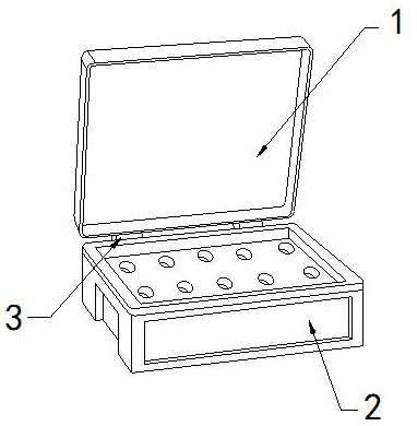
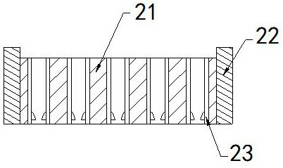
[0028] For example figure 1 -example Figure 5 Shown:

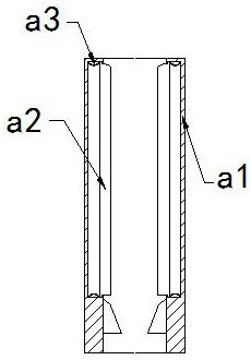
[0029] The present invention provides a sample storage device for ecological environment monitoring. Connected with the connecting block 3; the storage box 2 includes a built-in plate 21, an outer frame 22, and a fixing slot 23, the built-in plate 21 is embedded in the inner position of the outer frame 22, and the fixing slot 23 runs through the built-in plate 21. internal location.

[0030] The fixing slot 23 includes a frame body a1, a force-bearing plate a2, and a booster piece a3, the force-bearing plate a2 is movably engaged with the inner wall of the frame body a1, and the booster piece a3 is installed on the force-bearing plate a2 Between the inner side of the frame body a1 and the inner wall of the frame body a1, there are two said force-bearing plates a2, and the inner walls of the left and right ends of the frame body a1 are evenly distributed symmetrically. The pressing can make the force-bearing plate a2 s...

Embodiment 2

[0036] For example Image 6 -example Figure 9 Shown:

[0037] The frame body a1 includes a combination frame c1, an absorption block c2, and a limit block c3. The absorption block c2 runs through the inner position of the limit block c3, and the limit block c3 is attached to the inner wall of the combination frame c1. In addition, the absorbing block c2 is made of polyester sponge material with strong water absorption, and the moisture on the surface of the limiting block c3 can be absorbed by the absorbing block c2.

[0038] The limiting block c3 includes a lower sliding plate c31, a receiving plate c32, and an elastic strip c33. The lower sliding plate c31 is movably engaged with the left side of the receiving plate c32, and the elastic strip c33 is installed on the lower sliding plate c31 and the receiving plate. Between the tops of c32, the lower sliding plate c31 is squeezed by the test tube inserted into the object, so that the lower sliding plate c31 can slide and de...


PUM


Abstract

The invention discloses a sample storage device for ecological environment monitoring. The structure includes a top cover, a storage box, and a connection block. The lower end of the top cover is hinged to the connection block, and the rear end of the storage box is connected to the connection block. The sheet can push the force plate to quickly reset outward along the frame, so that the impact block inside the built-in cavity can follow the inertial force to slide outward along the inner side of the connecting block, so that the impact block can impact the inner wall of the frame Vibration, so that the surface of the board can be vibrated and the sand attached to the surface is shaken off. The thrust generated by the test tube inserted into the fixed groove again can make the lower board slide obliquely downward along the receiving plate. The thrust generated by the lower plate can make the lower plate quickly reset upward along the receiving plate, so that the lower plate can generate impact vibration with the inner wall of the receiving plate to shake off the silt on the outer surface of the lower plate.

Description

technical field [0001] The invention relates to the field of environmental monitoring, in particular to a sample storage device for ecological environment monitoring. Background technique [0002] The sample storage box for ecological environment monitoring is mainly a device for storing test tubes for ecological environment monitoring. The water source samples are collected through test tubes, and then stored in a centralized manner inside the sample storage box for ecological environment monitoring, so as to facilitate rapid detection in the later stage. Based on the above Description The inventors found that the existing sample storage device for ecological environment monitoring mainly has the following deficiencies, such as: [0003] Since the water in some waters contains a lot of sediment, the surface of the test tube is easy to adhere to the surface of the test tube when scooping up the water source sample. The sediment on the surface stays in the fixing tank, and i...

Claims


Application Information

Patent Timeline
Patent Type & Authority Patents(China)
IPC IPC(8): B65D25/02B65D25/10B65D25/52B65D85/30F26B5/16B08B7/02
CPCB65D25/02B65D25/101B65D25/52B65D85/30B08B7/02F26B5/16
Inventor 任亮张振江
Owner 河北省廊坊生态环境监测中心
Learn More