
On-film transplanting machine

A technology of transplanting machine and machine body, which is applied in the field of transplanting machines, and can solve problems such as high soil viscosity, soil squeezed into the seedling guide tube, and slow water evaporation

Pending Publication Date: 2021-06-08
灵宝砥砺农业科技有限公司
View PDF0 Cites 0 Cited by
  • Summary
  • Abstract
  • Description
  • Claims
  • Application Information

AI Technical Summary

Problems solved by technology

[0003] Due to the slow evaporation of water inside the film-covered soil, the soil rich in water is more viscous. If the seedling guide head of the film-covered transplanter is inserted into this type of soil, it is easy for the soil to squeeze into the inside of the seedling guide tube. As a result, the inside of the seedling guide tube is blocked, and the normal conduction of the crop seedlings cannot be performed.

Method used


Image

  • On-film transplanting machine
  • On-film transplanting machine
  • On-film transplanting machine

Examples


Embodiment 1

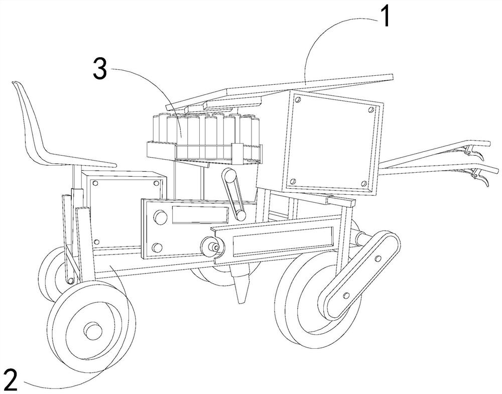
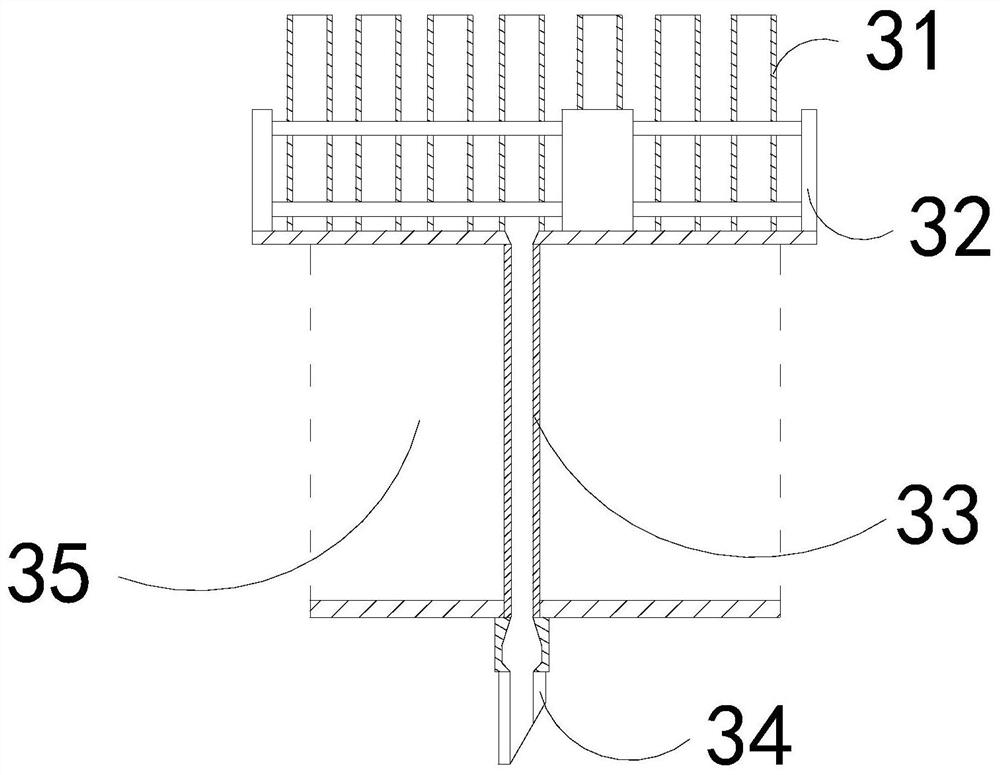
[0028] For example figure 1 -example Figure 5 Shown:

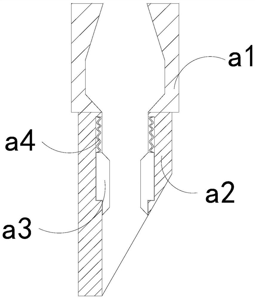
[0029] The invention provides a transplanting machine on a film, the structure of which includes an upper plate 1, a body 2, and a transplanting mechanism 3, the bottom of the upper plate 1 is connected with the upper end of the body 2, and the transplanting mechanism 3 runs through In the inner position of the body 2; the transplanting mechanism 3 includes a feeding pipe 31, a rotating disk 32, a fixed pipe 33, a seedling guide 34, and a partition 35, and the bottom of the feeding pipe 31 is installed on the inner wall of the rotating disk 32 At the bottom position, the bottom of the rotating disk 32 is welded to the upper end of the partition plate 35, the upper end of the fixed pipe 33 is embedded in the inner position of the rotating disk 32, and the top of the seed guide 34 is embedded and connected with the fixed pipe 33.

[0030] Wherein, the guide head 34 includes a frame a1, a lower frame a2, a sliding plate a3...

Embodiment 2

[0036] For example Figure 6 -example Figure 9 Shown:

[0037] Wherein, the grasping force groove a32 includes an extension block c1, a linkage rod c2, an extension bar c3, and a rear frame c4, the left side of the extension block c1 is connected with the right side of the linkage rod c2, and the linkage The rod c2 is slidably matched with the inside of the rear frame c4, and the push bar c3 is installed between the inner wall of the rear frame c4 and the left side of the linkage rod c2, and the vibration generated by the expansion and contraction of the mechanism can make the extension block c1 The linkage rod c2 slides outward along the rear frame c4 under cooperation, so that the overhanging block c1 can push out the soil inside the rear frame c4.

[0038] Wherein, the overhanging block c1 includes a central connection plate c11, an external extrusion strip c12, and a side swing plate c13, and the external extrusion strip c12 is fixed between the side of the central connec...


PUM


Abstract

The invention discloses an on-film transplanting machine. The on-film transplanting machine structurally comprises an upper placing plate, a machine body and a transplanting mechanism; the bottom of the upper placing plate is connected with the upper end of the machine body; and the transplanting mechanism penetrates through the inner position of the machine body. Through upward thrust generated by soil on a sliding plate, the sliding plate can upwardly slide and ascend along a lower connecting frame; the sliding plate can be downwardly pushed by a boosting strip to slide and reset after a seedling guiding head leaves the soil, so that the soil can be downwardly brought out by the sliding plate; an outwardly-extending block can outwardly slide and extend out along a rear frame under the cooperation of a linkage rod through vibration generated by up-and-down stretching of the seedling guiding head; and side swing plates can be unfolded towards two sides along a middle connecting plate through reverse thrust generated by the soil on the side swing plates when the outwardly-extending block extends out, so that the side swing plates can push the soil around the outwardly-extending block to be loosened, and the soil in a grabbing groove can be rapidly shaken out.

Description

technical field [0001] The invention relates to the field of transplanting machines, in particular to a film-on-film transplanting machine. Background technique [0002] The transplanting machine on the film is mainly used for transplanting crops on the film-covered land. The user puts the crop seedlings on the seedling tray into the feeding tube, and then guides the crop seedlings downward through the feeding tube, thereby To enable the seedling guide to dig out the pit on the soil and introduce the crop seedlings into the pit for transplanting. Based on the above description, the inventor found that the existing transplanting machine on the film mainly has the following deficiencies, for example: [0003] Due to the slow evaporation of water inside the film-covered soil, the soil rich in water is more viscous. If the seedling guide head of the film-covered transplanter is inserted into this type of soil, it is easy for the soil to squeeze into the inside of the seedling gu...

Claims


Application Information

Patent Timeline
Patent Type & Authority Applications(China)
IPC IPC(8): A01C11/02
CPCA01C11/02A01C11/025
Inventor 张国昌
Owner 灵宝砥砺农业科技有限公司
Learn More